I/Q Tuning Measurement Description
Last updated: December 3, 2008
How is an I/Q Tuning Measurement Made?
The I/Q Tuning measurement is used in the production process (normally at mobile pre-test) where the I/Q modulator of the mobile is being calibrated. The measurement is normally performed with the mobile station in test mode and transmitting a GMSK modulated sequence of all 0s or all 1s. The mobile can be transmitting either a bursted signal or a continuous wave signal. I/Q Tuning is not an ETSI specified measurement.
| NOTE |
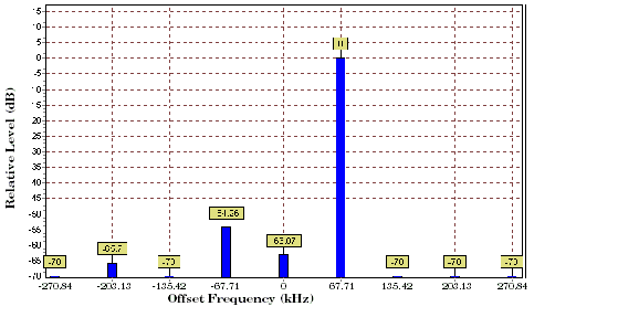
The carrier frequency is shifted up or down 67.7083 kHz by transmitting a sequence of all 0s (+67.7083 kHz) or all 1s (-67.7083 kHz). The accuracy of the mobile's I/Q modulator is determined by measuring the level of spurious signals relative to the desired signal (the desired signal being the carrier frequency +/-67.7083 kHz). The signals the test set measures are: the carrier frequency (Fc); Fc+/-67.7083 kHz; Fc+/-135.417 kHz; Fc+/-203.125 kHz and Fc+/-270.833 kHz. These signals are measured at the RF IN/OUT port.
The figure below shows a typical spectrum generated by a mobile transmitting a sequence of all 0s. The peak at the +67.7083 kHz offset is the one used as the reference.
The I/Q Tuning measurement also allows you to make an additional relative power measurement at any frequency you want between -13.0 MHz to -1.0 MHz and +1.0 MHz to +13.0 MHz relative to the carrier frequency.
Single or Multi-Measurements
The I/Q Tuning measurement can return either single or averaged measurement results.
-
If you set the multi-measurement state OFF then only a single measurement is made at each offset.
- If you set the multi-measurement state ON, and the multi-measurement count number to a value greater than one, then multiple measurements are made at each offset. The returned results are an average of these measurements.
Types of Signals I/Q Tuning can Measure
I/Q Tuning measurements can be made on these types of input signals.
I/Q Tuning Input Signal Requirements
The I/Q Tuning measurement will complete and meet its measurement accuracy specifications under the following input signal conditions.
Trigger Source
The trigger source depends on the type of input signal.
| Recommended Trigger Source | |
|---|---|
