Frequency Stability Measurement Description
Last updated: December 3, 2008
Description
How is a Frequency Stability measurement made?
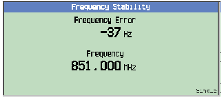
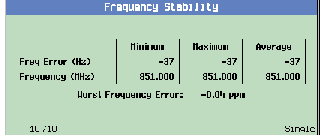
The Frequency Stability measurement displays the frequency of an RF signal applied to the test set's front panel RF IN/OUT input port. After each measurement the input signal's absolute RF freqency is displayed with 1000 Hz resolution on the test set's front panel and 1 Hz resolution when queried over the GPIB.
The absolute RF signal frequency obtained during each Frequency Stability measurement is compared to the expected (measurement downconverter) frequency of the test set's measuring receiver. The difference between the expected frequency and the measured frequency is displayed as frequency error with 1 Hz resolution.
If the device under test is a mobile station on a call, the expected frequency can be automatically set by the base station emulator (using the RF Channel setting).
If the device under test is not on a call, the expected frequency must be set by manually controlling the receiver (manual measurement frequency).
Operating Considerations
Front Panel Access
Frequency Stability measurements are accessed manually by pressing the front-panel Measurement selection key.
Input Signal Requirements
The Frequency Stability measurement is designed to measure non-bursted analog signals. For example, this measurement can be made on an AMPS cellular mobile station while it is on an active AVC (analog voice channel) with or without SAT or other frequency modulation. It is not desiged to measure AM (amplitude modulated) signals.
When a mobile station is on a call, the test set has the ability to predict the power level and frequency that is present on the RF input and automatically adjust attenuator and measurement downconverter settings. However, for test operating modes or CW (continuous wave) the test set is not functioning as a base station emulator. In the absence of call control, it is likely that the test set's receiver will need to be manually tuned to the input signal.
To meet Frequency Stability measurement performance specifications, the input signal must be:
Related Topics
Programming a Frequency Stability Measurement
Frequency Stability Measurement Troubleshooting

