Status Subsystem Overview
Last updated: September 2, 2009
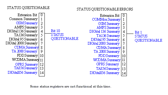
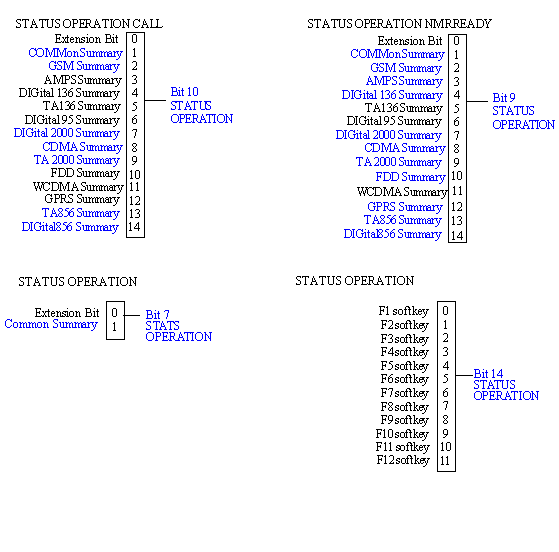
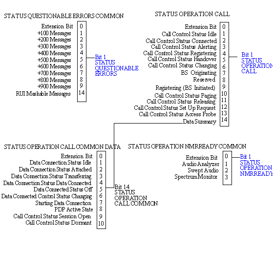
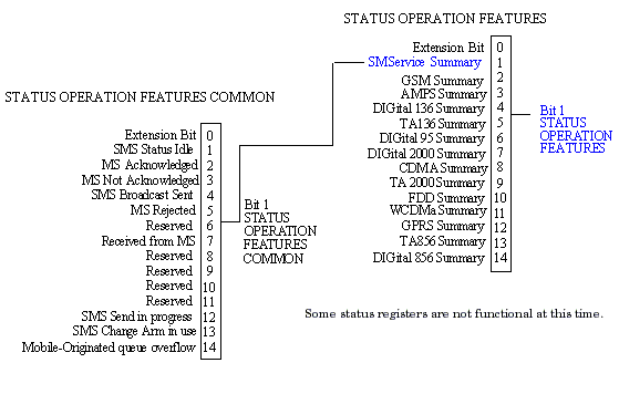
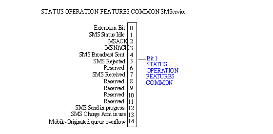
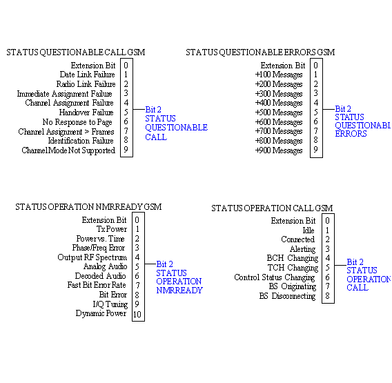
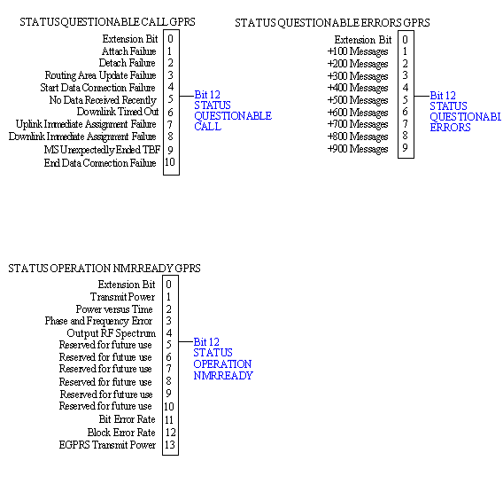
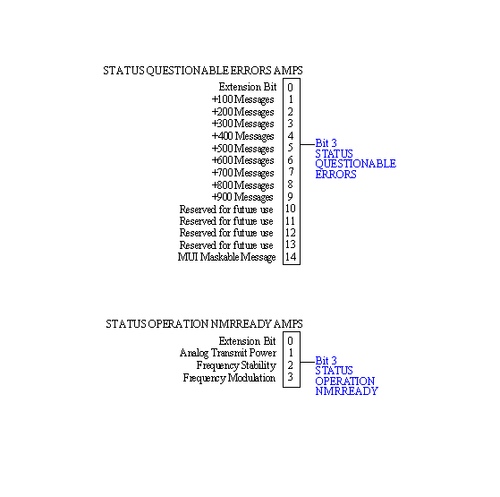
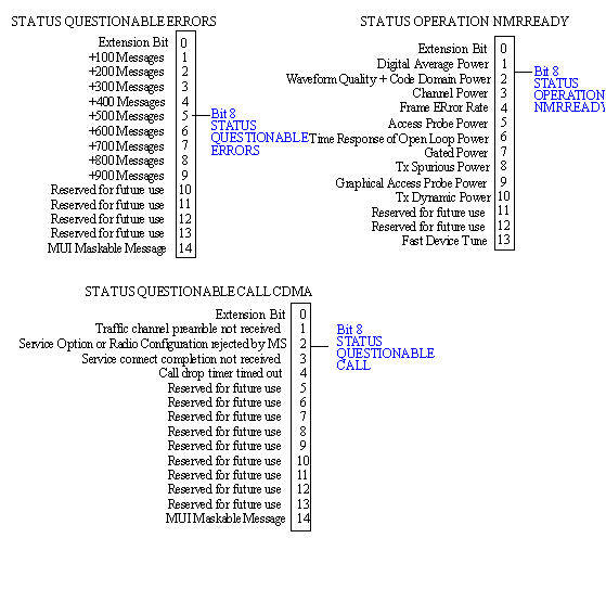
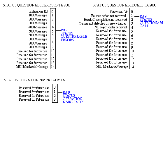
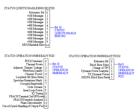
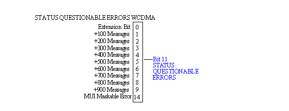
The following pages present an overview of the entire status subsystem, including applications which may or may not be loaded in your test set.
Description
Overview of STATus Reporting Structure
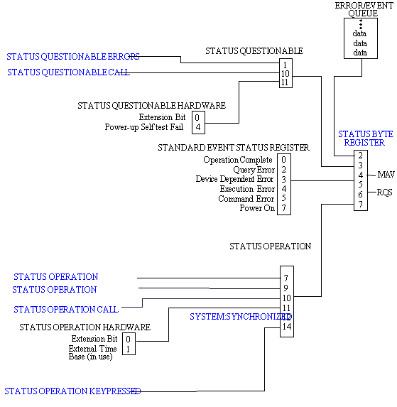
Status Data Structure - Register Model
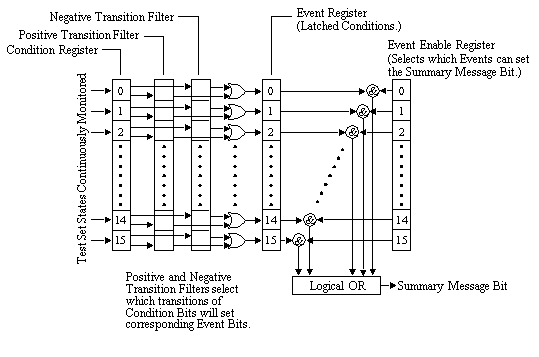
The generalized status register model consists of a Condition Register, Transition Filters, an Event Register, an Enable Register, and a Summary Message Bit.
Condition Register
A condition is a test set state that is either TRUE or FALSE (a GPIB command error has occurred or a GPIB command error has not occurred). Each bit in a Condition Register is assigned to a particular test set state. A Condition Register continuously monitors the hardware and firmware states assigned to it. There is no latching or buffering of any bits in a Condition Register; it is updated in real time. Condition Registers are read-only. Condition Registers in the test set are 16 bits long and may contain unused bits. All unused bits return a zero value when read.
Transition Filters
In the test set, the Transition Filters are implemented as two registers: a 16-bit positive transition (PTR) register and a 16-bit negative transition (NTR) register.
For each bit in the Condition Register, a Transition Filter bit determines the state transitions which will set a corresponding bit in the Event Register. Transition Filters may be set to pass positive transitions (PTR), negative transitions (NTR) or either (PTR or NTR). A positive transition refers to a condition bit which has changed from 0 to 1. A negative transition refers to a condition bit which has changed from 1 to 0.
A positive transition of a bit in the Condition register will be latched in the Event Register if the corresponding bit in the positive transition filter is set to 1. A positive transition of a bit in the Condition register will not be latched in the Event Register if the corresponding bit in the positive transition filter is set to 0.
A negative transition of a bit in the Condition register will be latched in the Event Register if the corresponding bit in the negative transition filter is set to 1. A negative transition of a bit in the Condition register will not be latched in the Event Register if the corresponding bit in the negative transition filter is set to 0. Either transition (PTR or NTR) of a bit in the Condition Register will be latched in the Event Register if the corresponding bit in both transition filters is set to 1. No transitions (PTR or NTR) of a bit in the Condition Register will be latched in the Event Register if the corresponding bit in both transition filters is set to 0.
Transition Filters are read-write.
Transition Filters are unaffected by a *CLS (clear status) command.
Transitions Filters are set to pass positive transitions (all 16 bits of the PTR register are set to 1 and all 16 bits of the NTR register are set to 0) at power on or after receiving the *RST (reset) command.
Event Register
The Event Register captures bit-state transitions in the Condition Register as defined by the Transition Filters. Each bit in the Event Register corresponds to a bit in the Condition Register. Bits in the Event Register are latched, and, once set, they remain set until cleared by a query of the Event Register or a *CLS (clear status) command. This guarantees that the application can't miss a bit-state transition in the Condition Register. There is no buffering; so while an event bit is set, subsequent transitions in the Condition Register corresponding to that bit are ignored. Event Registers are read-only. Event Registers in the test set are 16 bits long and may contain unused bits. All unused bits return a zero value when read.
Event Enable Register
The Event Enable Register defines which bits in the Event Register will be used to generate the Summary Message. Each bit in the Enable Register has a corresponding bit in the Event Register. The test set logically ANDs corresponding bits in the Event and Enable registers and then performs an inclusive OR on all the resulting bits to generate the Summary Message. By using the enable bits the application program can direct the test set to set the Summary Message to the 1 or TRUE state for a single event or an inclusive OR of any group of events. Enable Registers are read-write. Enable Registers in the test set are 16 bits long and may contain unused bits which correspond to unused bits in the associated Event Register. All unused bits return a zero value when read and are ignored when written to. Enable Registers are unaffected by a *CLS (clear status) command or queries.
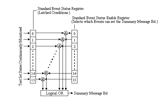
Standard Event Status Register Model
Summary Message Bit
The Summary Message is a single-bit message which indicates whether or not one or more of the enabled events have occurred since the last reading or clearing of the Event Register. The test set logically ANDs corresponding bits in the Event and Enable registers and then performs an inclusive OR on all the resulting bits to generate the Summary Message. By use of the enable bits, the application program can direct the test set to set the Summary Message to the 1, or TRUE, state for a single event or an inclusive OR of any group of events.
The Summary Message is TRUE, logic 1, if the register contains some information and an enabled event in the Event Register is set TRUE.
The Summary Message is FALSE, logic 0, if the queue is empty and no enabled events are TRUE. Registers can be cleared by reading all the information from the queue. Registers can also be cleared using the *CLS (clear status) command.
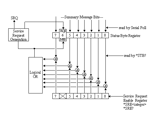
Service Request Enabling Register Model
Status Byte Register
The Status Byte Register is an 8 bit register that provides single bit summary messages, each summary message summarizes and overlaying status data structure. Summary messages always track the current status of the associated status data structure. Service request enabling determines if one or more of the summary messages will generate a message. Device status reporting is defined in IEEE 488.2-1992, 11.1.
The Status Byte Register contains the STB and RQS (or MSS) messages from the test set. The Status Byte Register can be read with either a serial poll or the *STB? common query. The value for bit 6 is dependent on which method used.
When reading with a serial poll the status byte and the RQS message are returned as a single data byte. The RQS message indicates if the SRQ is TRUE. The Status Byte Register is not affected by a serial poll, the RQS is set to FALSE when polled.
The *STB? query allows you to read the status byte and the MSS. The response represents the sum of the binary weighted values of the Status Byte Register from bit 0-5 and 7.
The Master Summary Status (MSS) message from bit 6 indicates when there is at least one reason for requesting service.
The Message Available (MAV) summary message from bit 4 is TRUE when there is a message is in the output queue.
The Status Byte Register is cleared with the *CLS common command. The output queue and the MAV are not affected by the *CLS command.
Service Request Enable Register
The Service Request Enable Register is an 8 bit register that enables corresponding summary messages in the Status Byte Register. Enabling the service request with the *SRE command allows you to choose which bits in the Status Byte Register will trigger a service request.
The Service Request Enable Register is read with the *SRE? query. The returned value is the sum of the binary weighted values of the Service Request Enable Register, with a range of 0 through 63 or 128 through 191.
