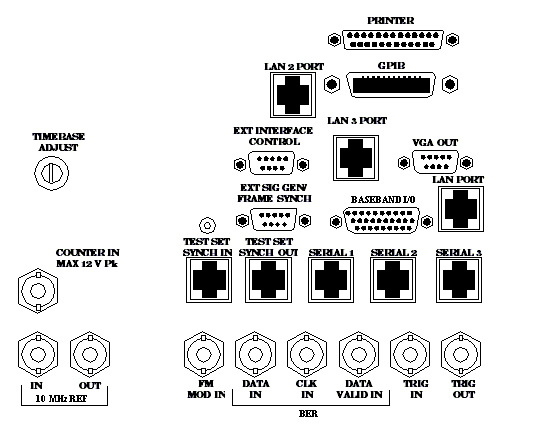
Rear Panel Connectors
Description

FM MOD IN
This BNC connector allows you to use an external signal to frequency modulate the test set's RF generator. It has a fixed sensitivity of 20 KHz/volt, and a frequency range of 100Hz to 20 KHz.
LAN PORT
This RJ-45 connector provides a connection for downloading firmware upgrades, new applications and for acquiring screen captures. In the lab application only, the LAN PORT is also used for protocol logging.
LAN 2 PORT
This RJ-45 connector provides a connection for transferring data to the test set and for establishing an external device connection between two test sets.
TIMEBASE ADJUST
This is the timebase adjust cover. Removing this screw allows access for timebase adjustment.
TRIG IN
This BNC connector provides the capability for you to trigger measurements or instruments from an external source. Setting the Trigger Source setting to External for measurements or instruments which support this feature causes the measurement or instrument to trigger when a positive-going TTL compatible pulse is applied to this connector. Currently, the only measurement or instrument which supports this feature is the Spectrum Monitor.
TRIG OUT
This BNC connector allows you to synchronize the test set to other equipment via a trigger signal.
VGA OUT
This DB-15 connector allows you to simultaneously route the test set's display to another monitor.
Related Topics
ETHERNET TO FRONT PANEL, LAN PORT: Configuring the Test Set's LAN
GPIB: Configuring the Test Set's GPIB
TRIG OUT: Trigger Output Setup
