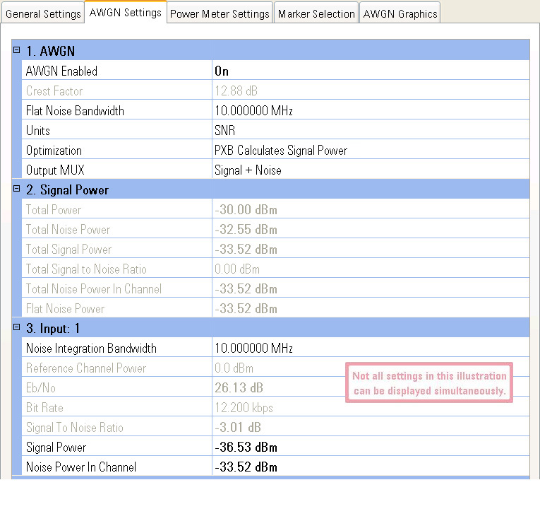
These settings control the AWGN attributes to be applied to the waveform output. AWGN is always added after any summing that takes place on the IO Node. When adding AWGN to the signal, the signal generator's ALC should be turned off to allow for power calibration by the PXB. Click the AWGN Graphics tab for an illustration that shows the relationship of the AWGN settings parameters described below.
Choices: On, Off
Default: Off
Activates the additive white Gaussian noise (AWGN) function. When turned on, the noise is added to the signal. Disabling the AWGN allows for maximum dynamic range in the signal. AWGN Enabled should not be used to switch noise on or off during a test. Use Output MUX instead.
When adding AWGN, the signal generator's ALC should be turned off to allow the Output MUX feature to work. If ALC is left on, the output power will be constant regardless of the Output MUX setting.
|
|
When AWGN is enabled, the PXB locks (disables) the connected signal generator's amplitude setting to ensure the correct power levels while playing waveforms. If you try to change the amplitude at the signal generator without first disabling AWGN, the PXB will change the amplitude back to the locked setting the next time you play a waveform. |
Default: 12.88 dB
Displays the peak to average ratio
of the AWGN. This ratio is a read-only value and may not be changed.
Range: 1001 Hz to 160 MHz
Default: 10 MHz
Resolution: 1 Hz
Sets the flat noise bandwidth of the AWGN. Flat noise bandwidth is sometimes referred to as noise bandwidth. The total noise bandwidth is always wider than the flat noise bandwidth. The flat noise bandwidth value must always be greater than the noise integration bandwidth. An illustration showing this parameter may be seen on the AWGN Graphics tab.
The maximum bandwidth value is limited to 80% of the output sample rate. The maximum  output sample rate
is dependent on the external instrument at the output.
output sample rate
is dependent on the external instrument at the output.
Choices: SNR, EbNo
Default: SNR
Selects how you want the signal to noise ratio to be determined. Your selection is based on your test requirements.
SNR
This selection allows you to directly input the desired signal-to-noise
ratio in dB.
Eb/No
This selection allows you to enter values for Eb/No,
Reference Channel Power, and Bit Rate settings that are displayed
when Eb/No is selected. These
setting values and the Integration Bandwidth
are used to calculate the signal-to-noise ratio using the equation:
SNR = Eb/No – Reference Channel Power –10 * Log10(Integration Bandwidth / Bit Rate)
Eb/No shows the ratio of the energy per bit (Eb) to the spectral power noise density (No). In a digital communications system, Eb/No is used as a measure of the signal to noise ratio in a way that is similar to the carrier to noise ratio (C/N). Eb/No lets you set the noise power relative to the power of a user selectable data channel (called the reference channel), which may have a bandwidth different than the integration bandwidth.
This selection may be changed even while the waveform is playing.
Choices: PXB Calculates Signal Power, PXB Calculates
Noise Power
Default Value: PXB Calculates Signal Power
Allows the PXB to calculate either the signal power or noise power while enabling the other two settings for user adjustment. Optimization is only usable when an Agilent signal generator is connected. Optimization uses the attributes of the connected instrument to determine the limits of the maximum signal, noise and total power.
There are several things to consider in order to preserve maximum dynamic range when using AWGN. It is always safe to reduce the total signal power from the initial total power used during a power calibration. There is a limited over range available so increasing the total signal power above this over range limit results in a warning message. Execute another power calibration if this warning occurs.
PXB Calculates Signal Power:
This selection instructs the PXB to calculate Signal Power based on the Signal to Noise Ratio and Noise Power In Channel settings.
If the Units setting is Eb/No, changing the Eb/No value will cause the PXB to recalculate the Signal Power value.
PXB Calculates Noise Power:
This selection instructs the PXB to calculate Noise Power In Channel based on the Signal to Noise Ratio and Signal Power settings. For best operation, set the signal to noise ratio to its minimum value.
If the Units setting is Eb/No, changing the Eb/No value will cause the PXB to recalculate the Noise Power In Channel value.
|
|
Only Signal To Noise Ratio can be set in configurations that output to an Agilent N5102A Digital Signal Interface Module or to a non-Agilent signal generator using the PXB's analog outputs. Total Power, Signal Power and Noise Power In Channel will not be calculated and will always be shown as -9999.99 dB. The Optimization setting is also unavailable and grayed out. |
Choices: Signal + Noise, Signal Only, Noise
Only
Default Value: Signal + Noise
Allows you to choose the desired signal components at the output from the PXB and view them while the AWGN is enabled. This feature allows you to view individual components of the signal so you may evaluate the signal components at the output of the PXB.
Signal + Noise
This choice allows the PXB to output the combined signal and noise.
Signal Only
This choice allows the PXB to output the signal while not outputting the
noise. This choice is not the
same as setting AWGN Enabled to
Off.
Noise Only
This choice allows the PXB to output the noise while not outputting the
signal.
This selection may be changed even while the waveform is playing.
Displays the total power (both signal power and noise power) available at the RF output of the signal generator after a power calibration has been performed. This is the signal generator's RF output amplitude value, which was set using the PXB's signal generator General Settings tab, SCPI commands, or the signal generator's front panel.
|
|
Only Signal To Noise Ratio can be set in configurations that output to an Agilent N5102A Digital Signal Interface Module or to a non-Agilent signal generator using the PXB's analog outputs. Total Power, Signal Power and Noise Power In Channel will not be calculated and will always be shown as -9999.99 dB. The Optimization setting is also unavailable and grayed out. |
Displays the power of the noise within the total noise bandwidth. The noise filter has some rolloff which contributes to the total power of the noise.
Displays the total output signal (carrier) power (dB). The total signal power is the combined power of all signals into the output IO block including the noise.
Displays the total output signal-to-noise ratio (dB).
Displays the noise power (dB or dBm, depending on the connected instrument) contained within the widest integration bandwidth. An illustration of this value may be seen on the AWGN Graphics tab.
Displays the power of the noise within the flat noise bandwidth.
|
|
Each signal that goes into an output block has its own uniquely numbered group of input parameters. Each input group is numbered to coincide with the numbering of the input channel it controls (see the block diagram for a visual representation of your configuration). |
Range: 1001 Hz to 160 MHz
Default: 10 MHz
Resolution: 1 Hz
Sets the bandwidth for the specified input signal over which the AWGN power is integrated. The noise integration bandwidth should be set equal to the signal bandwidth, and must be less than or equal to the flat noise bandwidth. When the noise integration bandwidth is changed to a value greater than the flat noise bandwidth, the flat noise bandwidth is also changed to the same value and an error is displayed. An illustration showing this parameter may be seen on the AWGN Graphics tab.
Range: –30 to 0 dB
Default: 0 dB
Resolution: 0.1 dB
Dependency: Displayed only when Units is set to Eb/No
Allows you to enter the power of the reference channel to be used for setting Eb/No. The signal to noise ratio is calculated using the equation:
SNR = Eb/No – Reference Channel Power – 10 * Log10 (Integration Bandwidth / Bit Rate)
Range: –190 to 113 dB
Default: 29.13640169 dB
Resolution: 0.1 dB
Dependency: Displayed only when Units is set to Eb/No
Allows you to enter the desired Eb/No value (the ratio of the energy per bit to the spectral power noise density) when you select to determine the signal to noise ratio using Eb/No. The signal to noise ratio is calculated using the equation:
SNR = Eb/No – Reference Channel Power – 10 * Log10(Integration Bandwidth / Bit Rate)
This selection may be changed even while the waveform is playing.
Range: 1 bps to 10
Default: 12.200
Resolution: 1 bps
Dependency: Displayed only when Units is set to Eb/No
Allows you to enter the bit rate of the reference channel when you select Eb/No as the SNR units. The signal to noise ratio is calculated using the equation:
SNR = Eb/No – Reference Channel Power – 10 * Log10(Integration Bandwidth / Bit Rate)
Range: Depends on the connected instrument, the noise power and signal power settings, and the incoming signal RMS
Default: 0 dB
Resolution: 0.1 dB
Dependency: Displayed only when Units is set to SNR
Sets the output signal-to-noise ratio (dB). The value is used to update the signal power settings before being output from the PXB to an external instrument. This setting is coupled with the Noise Power In Channel and Signal Power settings and balanced with other signals coming into the output IO block by the Noise Integration Bandwidth setting.
|
|
This selection may be changed even while the waveform is playing; however, large changes (>30 dB) may result in inaccurate power until the PXB has done a power calibration. |
Range: Depends on the connected instrument, the noise power and signal power settings, and the incoming signal RMS
Resolution: 0.1 dB
Sets the output signal (carrier) power (dB). The signal powers of all inputs to a given IO block are coupled, since they all affect a single upconverter. An illustration showing this parameter may be seen on the AWGN Graphics tab. The signal power setting assumes the Integration Bandwidth power has been correctly set by the user. This setting is coupled with the Signal To Noise Ratio and Noise Power In Channel settings.
This setting is read-only when AWGN Optimization is set to PXB Calculates Signal Power.
|
|
This setting can not be changed while the waveform is playing. |
|
|
Only Signal To Noise Ratio can be set in configurations that output to an Agilent N5102A Digital Signal Interface Module or to a non-Agilent signal generator using the PXB's analog outputs. Total Power, Signal Power and Noise Power In Channel will not be calculated and will always be shown as -9999.99 dB. The Optimization setting is also unavailable and grayed out. |
Range: Depends on the connected instrument, the noise power and signal power settings, and the incoming signal RMS
Resolution: 0.1 dB
This command sets the output noise power within the integration bandwidth (dB or dBm, depending on the connected instrument) with AWGN applied. An illustration showing this parameter may be seen on the AWGN Graphics tab. This setting is coupled with the SNR and signal power settings and balanced with other signals coming into the output IO block by the Noise Integration Bandwidth setting.
This setting is read-only when AWGN Optimization is set to PXB Calculates Noise Power.
|
|
This setting can not be changed while the waveform is playing. |
|
|
Only Signal To Noise Ratio can be set in configurations that output to an Agilent N5102A Digital Signal Interface Module or to a non-Agilent signal generator using the PXB's analog outputs. Total Power, Signal Power and Noise Power In Channel will not be calculated and will always be shown as -9999.99 dB. The Optimization setting is also unavailable and grayed out. |
General
Settings
Marker Selection
AWGN Graphics