TTI Mode Configuration
Last updated: September 1, 2009
This section is applicable to the EGPRS lab application and test application with a required feature license.
The TTI mode controls the data transfer latency of a PDTCH block. The two values that the TTI mode can be set are RTTI (Reduced Transmission Time Interval) and BTTI (Basic Transmission Time Interval). The data transfer latency is halved to approximately 10ms when using RTTI mode compared with BTTI. In RTTI mode, you can also select the USF mode and coding scheme to be used for control messaging.
BTTI
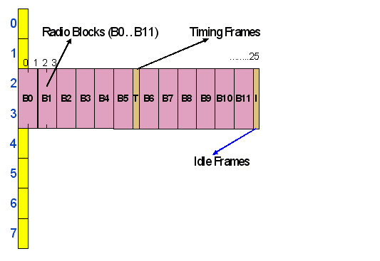
In the EGPRS system before Release 7 of the 3GPP standards, the data transfer latency is referred to as transmission time interval (TTI), which is classified as the Basic Transmission Time Interval (BTTI). With BTTI-based transfer, a PDTCH block in the PDTCH multiframe is transmitted across 4 consecutive frames on a single PDTCH physical channel as shown in the figure below.

Since a frame is approximately 4.615ms, the 4 frames gives a TTI of 20ms in a given direction of transfer.
RTTI
Release 7 of the 3GPP standards introduces the capability to reduce the TTI on EGPRS connections by pairing two PDTCH physical channels on different timeslots for data transfer. Usually the pairing timeslots have all frequency characterization in common. In this configuration, defined as Reduced TTI (RTTI), a PDTCH block interleaved over 4 bursts is transmitted on both PDTCHs in the PDTCH-pair across 2 frames as shown in the figure below. Since the number of frames required for transmission has halved, the TTI is halved to approximately 10ms.
The PDTCH timeslots are grouped into pairs for TBF transfer when the TTI mode is configured to RTTI. Furthermore the TTI mode of the downlink and uplink TBFs must be the same. Therefore only multislot configurations with both an even number of downlink and uplink timeslots shall be valid for RTTI mode.
The TTI mode remains BTTI if an attempt is made to change the TTI mode to RTTI when an invalid multislot configuration is configured. Conversely, if an attempt is made to set an invalid multislot configuration when the TTI mode is currently set to RTTI, the new multislot configuration is applied while the TTI mode shall be forced to BTTI.
RTTI USF Mode
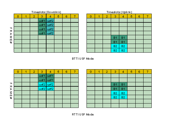
The USF Mode is signaled to the mobile station during Packet Uplink Assignment/Reassignment process. The two USF modes that can be selected for an RTTI configuration are BTTI USF mode and RTTI USF mode.
-
BTTI USF mode
In the RTTI configuration using BTTI USF mode, a given USF is interleaved over the 4 bursts associated with a PDTCH. The USF on the lowest PDTCH of a PDTCH-pair allocates resource in the first reduced radio block period of the next basic radio block period, and the USF on the highest PDTCH of a PDTCH-pair allocates resource for the second reduced radio block period of the next basic radio block period. (Here assume the Assigned USF Granularity is set to 1, otherwise each USF allocates 4 reduced block periods in the same position of consecutive basic radio block periods)
In the BTTI USF mode, the coding scheme of MCS-0 is used for control messaging.
-
RTTI USF mode (CS1)
In the RTTI configuration using RTTI USF mode, a separate USF is associated and interleaved over each reduced radio block on the downlink. The USF assigned in the first reduced radio block period on the downlink assigns resource for the second reduced radio block period on the uplink in the same basic radio block period. The USF assigned during the second reduced radio block period on the downlink assigns resource for the first reduced radio block period on the uplink in the next reduced radio block period.
In the RTTI USF mode (CS1), the coding scheme of CS-1 is used for control messaging.
-
RTTI USF mode (MCS-0))
The RTTI USF mode (MCS-0) is the same as RTTI USF mode (CS1) with the only exception that the coding scheme of MCS-0 is used for control messaging.
Configurable Parameters
-
TTI Mode
The TTI Mode allows the selection of whether BTTI or RTTI mode is used for the TBF transmission. The GPIB command to set this parameter is CALL:(PDTCH|PDTChannel):TTI[:MODE] .
-
RTTI USF Mode
The RTTI USF Mode allows the selection of the USF mode to use for an RTTI configuration, and for the case of RTTI USF mode, also whether CS-1 or MCS-0 is used for control messaging. The GPIB command to set this parameter is CALL:(PDTCH|PDTChannel):USFlag:RTTI[:MODE] .
-
USF by Burst
When the RTTI USF Mode is set to BTTI, each uplink burst present in the Multislot Configuration can have a USF selected, each USF can be the same as any other selected USF or it can be different, the USFs will be used in ascending order to match the uplink timeslots.
When the RTTI USF Mode is set to RTTI, the USFs can only be selected on a per-pair basis, the USF used for each pair will be taken from the odd numbered bursts (the first burst of each pair), thus even numbered bursts will not be available.
The GPIB command to set those parameters are CALL:(PDTCH|PDTChannel):USFlag:BURSt[1]|2|3|4|5|6:STATe , CALL:(PDTCH|PDTChannel):USFlag:BURSt[1]|2|3|4|5|6:VALue and CALL:(PDTCH|PDTChannel):USFlag:BURSt[1]|2|3|4|5|6[:SVALue]
-
RTTI with gamma settings
For BTTI mode, you can set MS Tx Level and Gamma for different burst respectively; For RTTI mode, since the timeslots are paired, essentially only the `odd' numbered burst settings for MS Tx Level and Gamma are relevant. The GPIB command to set this parameter is CALL:(PDTCH|PDTChannel):DTMode:MS:GAMMa:BURSt<[1]|2|3|4>[:SELected] .
How to set the TTI mode?
The following procedure details how to access and configure the TTI mode.
- Press CALL SETUP .
-
Press
PDTCH parms( F9 ). -
Press the
More
key on the lower right corner to display the
PDTCH parms (3 of 3). -
Press
TTI Mode( F7 ). Use the knob to select the TTI mode that you want.
The following procedure details how to access and configure the RTTI USF mode parameter.
- Press CALL SETUP .
-
Press the
More
key on the lower left corner to display the
Control menu (2 of 3). -
Press the
Protocol Controlsoftkey ( F4 ) to display a list of protocol layers. -
Press the
RLC/MACsoftkey ( F2 ). -
Press the
MAC controlsoftkey ( F2 ), use the knob to highlight and set theRTTI USF mode.
Operating Considerations
The RTTI configuration is only applicable in Active Cell (EGPRS), EGPRS BCH+PDTCH and EGPRS BCH+TCH+PDTCH operating mode. However, parameters associated with RTTI can be changed in other operating modes, but do not effect the test set's operation until the operating mode is changed to the above values.
When the TTI mode is set to RTTI, performing the following measurements will result in the measurement returning an `Unsupported Configuration' integrity indicator value.