How Do I Set Up and Use the Frequency Hopping Feature?
Last updated: December 2, 2008
This section is only applicable to the lab applications.
The following procedures assume the BCH Parameters for the Cell Band are set up correctly for your mobile station and the appropriate RF IN/OUT Amplitude Offsets have been set to the offset loss between the mobile station and the test set.
This section details the manual operation procedures for:
- Changing the Cell Allocation (CA) Table
- Setting up Frequency Hopping for GSM Traffic Channels
- Setting up Frequency Hopping for GPRS Packet Data Channels
- Setting up Frequency Hopping for EGPRS Packet Data Channels
- Viewing Frequency Hopping with the Spectrum Monitor
Changing the Cell Allocation (CA) Table
The CA Table lists all the channels available to the cell. The entries in the CA Table are important because the MA Tables can only use channels that are in the CA Table. The following procedure details how to change the CA Table.
- Press the CALL SETUP key.
-
Press
Operating Mode( F1 ) and chooseCell Offfrom the menu. -
Press
Cell Info( F6 ) -
Press
Cell Lists( F4 ). -
Press
CA Table( F2 ). TheCA Tablemenu that appears should look similar to the figure below.Note: The entries in the CA Table below contains the test set's default values.
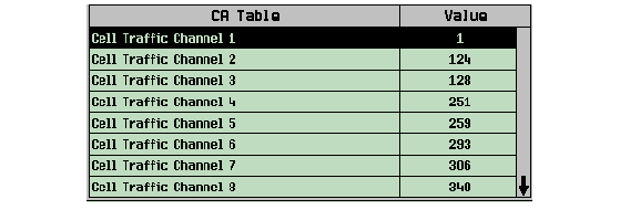
TheNOTE Operating Modemust beCell Offin order to change any values in theCA Table. If theOperating Modeis notCell Offall the entries in theCA Tablewill be gray.
Setting up Frequency Hopping for GSM Traffic Channels
- Press the CALL SETUP key.
-
Press
Operating Mode( F1 ) and selectActive Cell(GSM, GPRS, or EGPRS) orGSM BCH+TCH -
Press
TCH Parameters( F8 ) -
Press the
More
key on the right side of the screen so
2 of 2is displayed. -
Press
Frequency Hopping( F11 ). -
Press
Freq Hopping( F7 ) and turn the state toOn. -
Press
HSN( F8 ) and choose a Hopping Sequence Number. -
Press
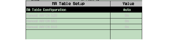
MA Table( F9 ). A menu similar to the figure below appears that shows all the ARFCNs that are currently in theMA Tablefor the selected band. The figure below is the defaultMA Tablefor the PCS band.-
To change the state of any ARFCN, you must first set the
MA Table ConfigurationtoManual.Notice when theMA Table Configurationis set toManualall of the table entries change from gray to black. -
To change the values that are in the
MA Table, you must change the Cell Allocation (CA) Table first by adding/changing ARFCNs for the desired band. See Changing the Cell Allocation (CA) Table for the manual operation procedure for changing theCA Table.
-
-
Press
Meas ARFCN( F11 ) to set the Measurement ARFCN. Use the knob to scroll through the choices for the Measurement ARFCN. - Originate a call between the test set and the mobile station.
-
View the frequency hopping. The
Spectrum Monitorthat is incorporated into the test set is a useful instrument for this purpose. See Viewing Frequency Hopping with the Spectrum Monitor for an example of how you might view frequency hopping. Note: TheTraffic Channel( F9 ) field under theTCH Parmsmenu disappears from the front panel when frequency hopping is enabled.
Setting up Frequency Hopping for GPRS Packet Data Channels
- Press the CALL SETUP key.
-
Press
Operating Mode( F1 ) and selectActive Cell(GPRS) orGPRS BCH+PDTCH. -
Press
PDTCH Parameters( F9 ) - Follow steps 4-9 in Setting up Frequency Hopping for GSM Traffic Channels .
- Start a data connection.
-
View the frequency hopping. The
Spectrum Monitorthat is incorporated into the test set is a useful instrument for this purpose. See Viewing Frequency Hopping with the Spectrum Monitor for an example of how you might view frequency hopping.
Setting up Frequency Hopping for EGPRS Packet Data Channels
- Press the CALL SETUP key.
-
Press
Operating Mode( F1 ) and selectActive Cell(EGPRS) orEGPRS BCH+PDTCH. -
Press
PDTCH Parameters( F9 ) - Follow steps 4-9 in Setting up Frequency Hopping for GSM Traffic Channels .
- Start a data connection.
-
View the frequency hopping. The
Spectrum Monitorthat is incorporated into the test set is a useful instrument for this purpose. See Viewing Frequency Hopping with the Spectrum Monitor for an example of how you might view frequency hopping.
Viewing Frequency Hopping with the Spectrum Monitor
This procedure assumes that the BCH parameter for Cell Band is set up correctly for your mobile station and that the appropriate RF IN/OUT Amplitude Offsets have been set to offset loss between the mobile station and the test set.
- Set up frequency hopping for a GSM, GPRS, or EGPRS connection. See Setting up Frequency Hopping for GSM Traffic Channels , Setting up Frequency Hopping for GPRS Packet Data Channels , or Setting up Frequency Hopping for EGPRS Packet Data Channels .
- Press Instrument Selection.
- Choose Spectrum Monitor from the Instrument Selection list.
- Select Frequency Span (F1) and set it to zero. The zero span mode of operation allows you to see whether or not an ARFCN was present in a particular frame.
-
Press the Trigger Setup (F4) and choose
Protocolfrom the Trigger Source list. - Press Time Span (F8) and set to 15 ms.
-
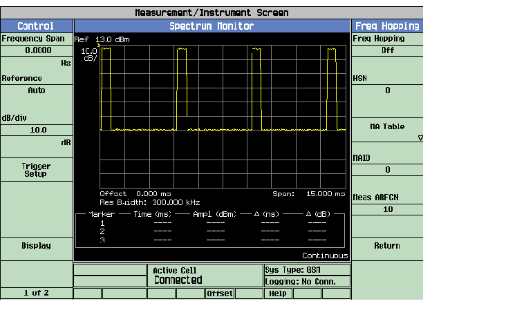
Press Trigger Arm (F3) to Continuous. You should see a screen similar to the figure below. The frequency should appear to be hopping as it changes in a cyclic or random way, depending on the setting for the HSN. The figure below is a plot of power vs. time when frequency hopping is enabled and the Measurement ARFCNs are 1 and 10 for the PGSM band.
-
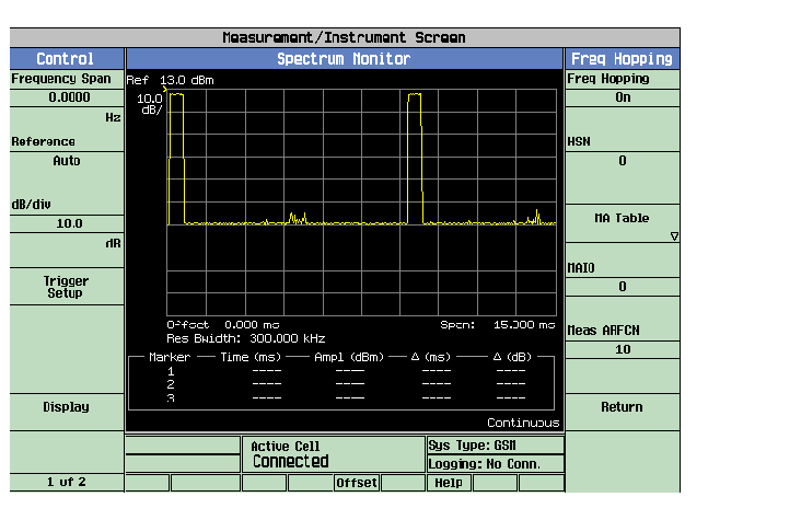
The figure below is a plot of power vs. time when frequency hopping is off and when the Measurement ARFCNs are 1 and 10 for the PGSM band.