Both MOD and RF must be enabled to generate a WiMAX output signal.
Before any measurements can be made, a link must be established between the Test Set and the Subscriber Station (SS). This is achieved by setting the appropriate frequency, power level, and attenuation on the Test Set and starting Base Station Emulation mode. The SS must also be capable of executing a Network Entry procedure in order to begin two way communications with the E6651A. The Network Entry procedure must be invoked from the SS using a Network Entry Application. Obtain this application from the SS vendor. A Network Entry application is typically applied from a control PC or from the SS itself.
To begin interfacing with the Subscriber Station (SS) in BSE mode:
Profile: First ensure the correct profile for the DUT has been selected.
Connect the E6651A and the SS: After starting the Test Set and selecting BSE modes, connect the Test Set to the SS using one or two (for MIMO operation) RF cables.
Set
the Test Set Frequency: Set the Test Set to the frequency used
by the SS.
Press the Frequency button.
Press Center and enter
the Center Frequency using the knob, arrow, numeric keys. Terminate your entry by pressing GHz,
MHz,
kHz,
or Hz
as required.
Set
the Output Power: The default output power of the E6651A is set
to -50 dBm to protect the subscriber station from damage.
It may be necessary to adjust the output power to an appropriate level,
determined by the subscriber station's specifications. To adjust the output
power:
Press Amplitude.
For Test Sets with more than one transmit path, press RF Select to select the required path, otherwise proceed at step 3.
Enter the desired level using the Knob or Numeric keys. When using the Numeric keys, press dBm to terminate the entry.
Set
the Input
Attenuation Value: The Test Set can attenuate the input signal
to protect it’s internal circuitry. Input attenuation totalling 59 dB
for option 503 Test Sets, and 62dB for option 506 can be set to protect
the Test Set from high input signal levels. It is also necessary to choose
suitable input attenuation to achieve the optimum internal signal-to-noise
ratio for measurement accuracy, whilst remaining below levels which cause
saturation and non-linear behaviour.
By setting the reference level (REF LVL) to that of the applied signal,
and setting Receiver Attenuation to Auto allows the E6651A to select the
optimum attenuation value.
For optimum measurement performance:
Press Amplitude > Receiver Attenuation to select [Auto].
Press Amplitude > REF LVL and adjust the value to that of the uplink signal.
Connect the MS to
the Test Set and adjust for synchronisation.
Fine tune the attenuation by:
Press Amplitude > Receiver Attenuation to select [Manual] and reduce the attenuation until the saturation indicator in the status window displays SAT in yellow. Note the attenuator setting. Note the value.
Now increase the attenuation by 3 dB.
The Attenuation is now configured for optimum measurement accuracy.
Switch
on Modulation: The Test Set modulates the output signal as described
in the Mobile WiMAX specification.
Press MOD On/Off
to turn on the modulation. For Test Sets with more than one signal path,
select the path(s) to be enabled by pressing RF
1 and/or RF 2.
Switch
on RF Power: The Test Set transmits the output signal at the frequency
and power level previously specified.
Press RF On/Off
to turn on the RF power. For Test Sets with more than one signal
path, select the path(s) to be enabled by pressing RF
1 and/or RF 2.
|
|
Both MOD and RF must be enabled to generate a WiMAX output signal. |
Start Base Station Emulation: To begin Base Station Emulation Mode, BS Emulator, Start.
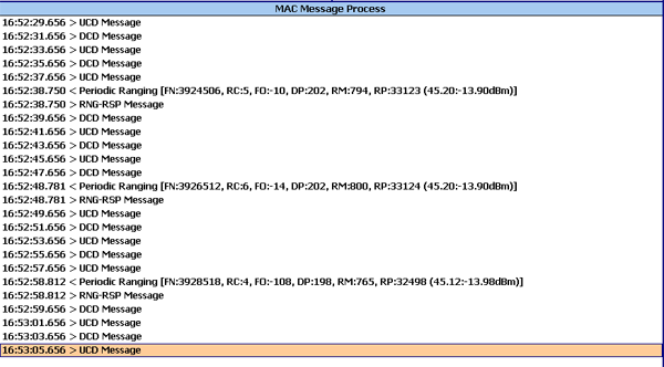
Establishing Two Way Communications With the SS: The SS must now execute a Network Entry procedure in order to begin two way communications with the E6651A.
After successfully establishing two way communications, various control messages between the E6651A and the SS are displayed in the Action Window, for example, periodic ranging messages.