Code Channel Time/Phase Error Measurement Description
Last updated: November 25, 2010
- How is a Code Channel Time/Phase Error measurement made?
- Code Channel Time/Phase Measurement Graphical Display
- Measurement Behavior
- Input Signal Requirements
- Key TIA/EIA-98-E Tests Using Code Channel Time/Phase Error Measurement
- Calibrating the Code Channel Time/Phase Error Measurement
How is a Code Channel Time/Phase Error measurement made?
This measurement is designed to analyze signals that contain a reverse pilot channel. A call must be connected with one of the following radio configurations selected:
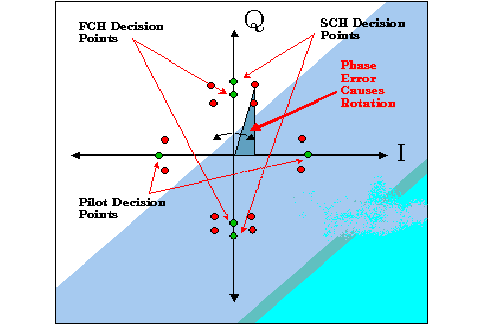
Each code channel timing and phase measurement tests the time and phase alignment of each code channel relative to the reverse channel pilot signal. The time error returns any offset, in nanoseconds, that is detected between the coding of each Walsh channel and the reverse channel pilot. The phase error measurement determines whether there is any phase difference that would cause a rotation in the I/Q constellation away from the decision points. See I/Q Constellation Showing Phase Error .
Code channel time/phase error measurements are made by sampling the down-converted input signal, then applying DSP (Digital Signal Processing) techniques to determine the original data input to the mobile station transmitter's Walsh spreading function for each channel. The DSP then generates a representation of what the "ideal" signal would be given the coding and data in use at the time of transmission. The ideal waveform is then compared with the waveform being measured to determine code channel time error and phase error.
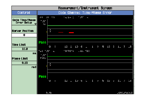
Code Channel Time/Phase Error Measurement Results lists the code channel time and phase measurement results:
| Code Channel Time/Phase Error |
|---|
| Code Channel Time |
| Code Channel Phase |
Code Channel Time/Phase Measurement Graphical Display
The Code Channel measurement displays the timing and phase error of reverse code channels. A marker can be positioned at any of the 16 (it's 64 when radio configuration is (Fwd11, Rvs8)) Walsh code channels along the graph's horizontal axis. The Marker position field setting applies to both the Time and the Phase error graphs.
Code Channel Time/Phase Error shows an example display for the Code Channel Time/Phase Error measurement under (Fwd 3, Rvs 3), (Fwd 4, Rvs 3) and (Fwd5, Rvs4). When the radio configuration is (Fwd11, Rvs8), the Code Channel Time/Phase Error results are based on 64-bits walsh function, and the X-Axis shows "0" on the left, "63" on the right, and "Spread Code" in the middle.
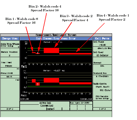
The IS-2000 system achieves high data rates by allowing supplemental channels to occupy multiple code channels. Each marker position displays one spread factor 16 code channel. To facilitate the display of high data rate channels occupying more than one marker positions in one contiguous (wide) bar, the Walsh code sequence along the graph's x-axis is displayed in "bit reversed" order to the marker position numbers 0 to 15. See Walsh Numbering on Code Channel Timing and Phase Graphs (RC=3, 4 or 5) .
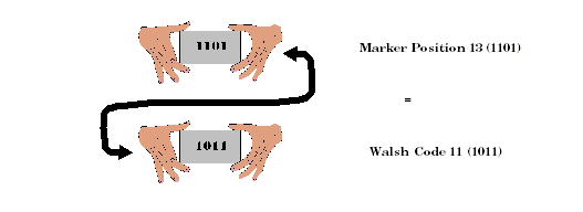
An example of bit reversal under RC3, RC4 and RC5 is shown in Walsh Channel Bit Reversal Marker Position 13 has a binary coded decimal value of 1101. If you reverse that sequence, the result is 1011. When 1011 is converted back to a decimal value, the result is Walsh code 11.
| 1 | 2 | 3 | 4 | 5 | 6 | 7 | 8 | 9 | 10 | 11 | 12 | 13 | 14 | 15 | ||
| 8 | 4 | 12 | 2 | 10 | 6 | 14 | 1 | 9 | 5 | 13 | 3 | 11 | 7 | 15 |
The timing and phase graphs, because of the bit-reversed order, can display channels with a spreading factor less than 16, such as the R-SCH (Reverse Supplemental Channel), using one bin 1 .
For example, Code Channel Timing Graph With R-SCH shows four active code channels displayed in four bins. In bin four, Walsh code channels 1, 3, 5, 7, 9, 11, 13, and 15 are all included in a single channel. If the Walsh numbering on the test set's display were sequential, then this channel would have to be displayed as eight bars, each separated by one Walsh code.
Measurement Behavior
Bin 0 corresponding with Walsh 0 will always return zero for Time Error zero and phase error because all other measurements are relative to the pilot channel, which is located at Walsh 0, bin 0.
Input Signal Requirements
The Code Channel Timing and Phase measurement meets or exceeds specifications when the following requirements are met:
- The frequency of the signal being measured must be in the range of 412 MHz to 483 MHz, 800 MHz to 960 MHz, or 1.7 GHz to 2.0 GHz, and within 100 kHz of the expected frequency.
- The signal level into the test set's RF IN/OUT connector must be in the range of -25 dBm to +37 dBm. The test set can autorange to a signal that is within +/- 9 dB of the expected input level (see RFANalyzer:AUTO:POWer[:SELected]? ).
Calibrating the Code Channel Time/Phase Error Measurement
The code channel time/phase error measurement is automatically calibrated during a channel power calibration. Follow the channel power calibration schedule and the code channel time/phase error measurement will be properly calibrated. Refer to Calibrating the Test Set for a description of channel power calibration.
Related Topics
Measuring Code Channel Time/Phase Error
Programming a Code Channel Time/Phase Measurement