Waveform Quality/Code Domain Measurement Description
Last updated: November 25, 2010
- How is a Waveform Quality/Code Domain Power measurement made?
- Waveform Quality/Code Domain Measurement Parameters
- Code Domain Power
- Graphical Waveform Quality
- Input Signal Requirements
- Key TIA/EIA-98-E Tests Using the Waveform Quality + Code Domain Measurement
- Calibrating the Waveform Quality + Code Domain Measurement
How is a Waveform Quality/Code Domain Power measurement made?
Each waveform quality measurement returns a number of measurements which includes:
- Rho, the percentage of signal energy that correlates with a perfect IS-2000 signal after time offset and frequency error have been removed.
- Code domain power (including the power and noise levels of each code channel transmitted by the mobile station).
- Walsh code of each active code channel.
- Spread factor of each active code channel.
- Code domain power and noise (the sum total of power and noise of each code channel transmitted by the mobile station).
Any time a call is connected, waveform quality measurements can be made. Any combination of service option, radio configuration, or data rate can be measured.
Waveform quality measurements are made by sampling the down-converted input signal, then applying DSP (Digital Signal Processing) techniques to determine the original data input to the mobile station transmitter's Walsh spreading function for each channel. The DSP then generates a representation of what the "ideal" signal would be given the coding and data in use at the time of transmission. The ideal waveform is then compared with the waveform being measured to determine the waveform quality.
Waveform Quality/Code Domain Power Measurements lists the Waveform Quality/Code Domain Power measurement results:
Multi-measurements (with statistical measurement results) are available for the Waveform Quality: Numeric Rho measurement. These include:
Waveform Quality/Code Domain Measurement Parameters
-
Multi-Measurement Count
When ON, this enables averaging of multiple waveform quality + code domain measurement results. For example, when multi-measurement count is set to 3, three waveform quality + code domain measurements are made sequentially and the results of all measurements are averaged to determine the final result. (See Statistical Measurement Results ).
-
Graphical Waveform Quality State
On - When the Graphical Waveform Quality State is set to On, the softkey Graphical Waveform Quality is available and displayed to give a graphical or numerical view of Chip EVM Graphical Display , IQ Constellation Graphical Display , and Waveform Quality Numerical Display .
Off - When the Graphical Waveform Quality State is set to Off, the softkey Graphical Waveform Quality will not be available and displayed, and the FETCh:WQUality:EVM:TRACe? will return 9.91E37 (NAN). The default value of Graphical Waveform Quality State is Off.
When the current view is Graphical Waveform Quality, setting the Graphical Waveform Quality State to OFF will cause the view change to Numeric Rho by force.NOTE
- Trigger Arm - (see Trigger Arm (Single or Continuous) Description ).
- Timeout Time/State - (see Timeouts ).
The Multi-Measurement Count is not applicable to the graphical Waveform Quality measurement. When Multi-Measurement Count is set to on, only the Chip EVM or IQ Constellation measurement results for the power control group during the last measurement will be returned.NOTE
Code Domain Power
The Code Domain Power Graphical Display
When making Code Domain Power measurements on the reverse supplemental channel, the data source PRBS (pseudo-random bit sequence) must be selected. See How Do I Change TDSO Supplemental Channel Information? .IMPORTANT
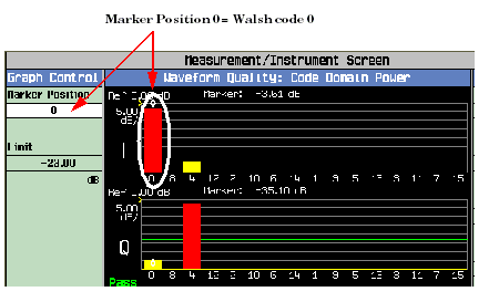
The Code Domain Power measurement displays the power and noise levels of reverse code channels. A marker can be positioned at any of the 16 Walsh code numbers. For example, Reverse Pilot Channel on I Channel shows the marker at marker position 0, which corresponds with Walsh code 0. The red bar represents the power level of the reverse pilot channel, which is always found on Walsh code 0 of the I channel graph. When the
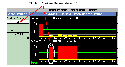
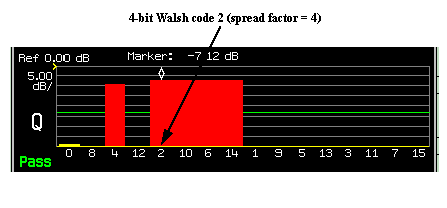
Radio Configis set to(Fwd11, Rvs8), there will be 64 bins on the X-Axis, "0" shows on the left, "63"on the right, and the narrowest bar is 1/4 of the narrowest bar when theRadio Configis set to(Fwd3, Rvs3). In addition, 1x advanced supports three ACK channels (R-ACK1, R-ACK2, R-ACK3).The Marker position field setting applies to both the I and the Q graphs. For example, the reverse fundamental channel is always located at Walsh code 4 of the Q channel graph. This channel corresponds with marker position 2, as shown in Reverse Fundamental Channel on Q Channel .
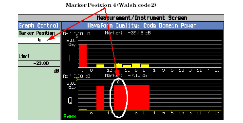
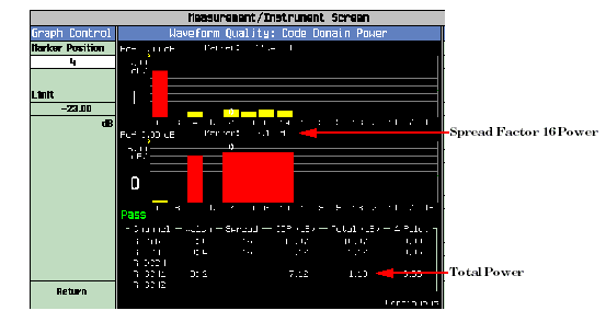
The power levels of reverse supplemental channels (R-SCH1 and R-SCH2) sometimes occupy more than one marker position. The number of marker positions the supplemental channels occupy is determined by data rate. Because of the order of Walsh codes along the horizontal axis, code channels that display higher data rate Walsh code channels combine together to form one contiguous (wide) bar. For example, Reverse Supplemental Channel on Q Channel shows a supplemental channel occupying marker positions 4, 5, 6 and 7. This supplemental channel was transmitting data at 76.8 kbps.
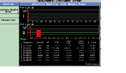
A typical display when radio configuration is set to (Fwd11, Rvs8) is shown below:
How Spread Factors Affect the Code Domain Display
The cdma2000 system achieves high data rates by allowing supplemental channels to occupy variable amounts of Walsh code space depending on the channel's data rate. The lowest ratio of occupied to available code space is 1/16 (1/64 when radio configuration is (Fwd11, Rvs8)), and these channels are said to have a spread factor of 16 (64 when radio configuration is (Fwd11, Rvs8)).
Each marker position displays the power or noise of one spread factor 16 code channel. If the supplemental channel being measured has a spread factor of less than 16, more than one marker position will be occupied, as shown in Spread Factor of Supplemental Channel Data Rates
Spread Factor of Supplemental Channel Data Rates Spread Factor Number of Occupied Marker Positions 16 1 38.4 kbps 8 2 76.8 kbps 4 4 153.6 kbps 2 8 2 bits Because each marker position displays only the power or noise of a spread factor 16 code channel, a method for calculating power in channels with spread factors of 8, 4, or 2 must be applied. See Computing supplemental channel power .
Computing supplemental channel power
Each marker position displays the power or noise of one spread factor 16 code channel. When measuring the code channel power of a supplemental channel occupying more than one marker position, the total power in the code channel must be calculated according to Supplemental Channel Power Calculation Add the value listed in the "Value to Add to R-SCH Power" column to the reported power value from the display.
For example, Total Supplement Channel Power shows the marker positioned on a 76.8 kbps supplemental channel and the marker value for the Q channel is -7.14 dB. Adding +6.02 dB to this value results in a total power of -1.12. Notice that a table is provided below the I and Q graphs that computes and displays total power for the supplemental channel (R-SCH1).
Obtaining Code Domain Power Results Programmatically
Obtaining code channel information programmatically by code channel name
One way to obtain code channel measurement results is to use commands that refer to code channels by name. These commands are:
- FETCh:WQUality:CDPower[16]:PILot[:REVerse]?
- FETCh:WQUality:CDPower[16]:FCHannel[:REVerse]?
- FETCh:WQUality:CDPower[16]:CCHannel:DEDicated[:REVerse]?
- FETCh:WQUality:CDPower[16]:SCHannel1[:REVerse]?
- FETCh:WQUality:CDPower[16]:SCHannel2[:REVerse]?
- FETCh:WQUality:CDPower64:PILot[:REVerse]?
- FETCh:WQUality:CDPower64:FCHannel[:REVerse]?
- FETCh:WQUality:CDPower64:SCHannel1[:REVerse]?
- FETCh:WQUality:CDPower64:SCHannel2[:REVerse]?
- FETCh:WQUality:CDPower64:ACKChannel1[:REVerse]?
- FETCh:WQUality:CDPower64:ACKChannel2[:REVerse]?
- FETCh:WQUality:CDPower64:ACKChannel3[:REVerse]?
Each of these code domain power queries returns the difference between the total code channel power and the reverse pilot channel level along with other values. Limits for this value are specified in the Code Channel to Reverse Pilot Channel Output Power Accuracy test in test standard TIA/EIA 98-E.
Obtaining code channel information programmatically by I/Q channel and bin number
One command provides a method for querying the pass/fail status of code domain power in the inactive code channels. This command is:
Limits for this value are specified in the Code Domain Power test in test standard TIA/EIA 98-E. Pass/fail limits are set up using the SETup:WQUality:CDPower[16]:IQINactive[:LIMit] , SETup:WQUality:CDPower64:IQINactive[:LIMit] command.
Code channel measurement results can be obtained using commands that refer to code channels collectively by I channel and Q channel designation. These commands are:
- FETCh:WQUality:CDPower[16]:ICHannel[:ALL]?
- FETCh:WQUality:CDPower[16]:QCHannel[:ALL]?
- FETCh:WQUality:CDPower64:ICHannel[:ALL]?
- FETCh:WQUality:CDPower64:QCHannel[:ALL]?
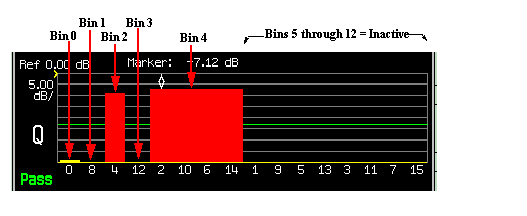
Each of these commands returns information for all code channels in either the I or Q channel, but the information is segmented into units referred as "bins" as shown in Bin Numbering System .
Bins are dynamically allocated to code channels depending on which code channels are active and the code channel spread factors. For example, if no code channels have spread factors less than 16, 16 bins will be assigned values. Code channel information can be obtained bin-by bin using the following commands:
Bins that are not active, like bins 0, 1, and 3 and 5 through 12 in the example above only contain noise power (yellow bars). Since this example has a supplemental channel that occupies four Marker Positions, and only one bin is needed to carry this code channel's information, the commands listed above will only return 13 out of a possible 16 bins of information. In the comma-separated string returned by these commands, the final three segments will consist of +9.91 E+37 (NAN).
Code channel information can be obtained bin-by bin using the following commands:
Relationship Between Spread Factors and Walsh Code Space
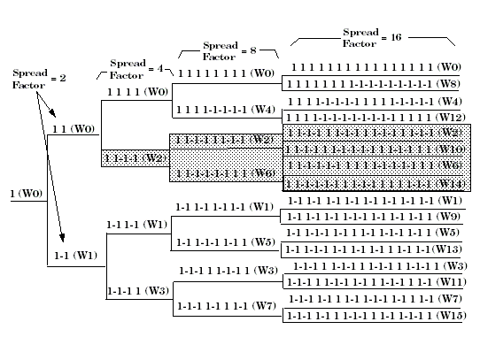
In Walsh Code Spread Factors , the highlighted bit sequences show the code space that Walsh 2 (W2) with a spread factor of four occupies. Following the tree from the highlighted bit sequence on the left side the following Walsh codes are all occupied by Walsh code 2 (W2) with a spread factor of four:
- Walsh code W2 with a spread factor 4
- Walsh code W2 with a spread factor 8
- Walsh code W6 with a spread factor 8
- Walsh code W2 with a spread factor 16
- Walsh code W10 with a spread factor 16
- Walsh code W6 with a spread factor 16
- Walsh code W14 with a spread factor 16
Note in Spread Factor 4 Code Space , the R-SCH on Walsh code 2 occupies four graphical elements, which amounts to 1/4 of the available code space.
Bit reversal
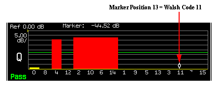
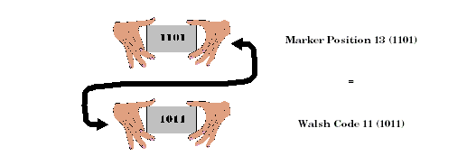
Note the order of the spread factor 16 Walsh codes are shown in 16 Bit Walsh Code Order . This order is derived from applying bit reversal to the decimal numbers 0 to 15. Consider Marker Position 13, which corresponds with Walsh code 11.
Marker Position 13 evaluates to a binary coded decimal value of 1101. If you reverse that bit sequence, the resulting pattern is 1011. When 1011 is converted back to a decimal value, the result is Walsh code 11, as shown in Walsh Channel Bit Reversal . This numbering system allows supplemental channels with higher data rates to be displayed as one contiguous block.
Graphical Waveform Quality
The Graphical Waveform Quality Display
The Graphical Waveform Quality Measurement is only applicable when the Graphical Waveform Quality State is On.NOTE
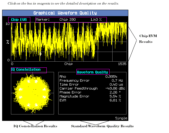
The Graphical Waveform Quality measurement gives a graphical view of the waveform quality of the AT. Three measurement results screen are available for Graphical Waveform Quality.
The IQ constellation diagram is always redrawn to reflect the latest Chip EVM settings. For example, if the chip EVM for chips 512 through 1023 are plotted, then the IQ constellation is shown for just chips 512 through 1023. The I and Q values for the IQ constellation all range between -1.0 and +1.0.
An example display for the Graphical Waveform Quality measurement results is show below.
Chip EVM Graphical Display
Chip EVM is the calculated EVM at each chip in the measured single power control group. Chip EVM is measured as a 1536 element array of 32-bit floating point numbers during a single power control group. The first element in the array corresponds to the measured EVM for the first chip in the measured power control group, the second element to the EVM for the second chip in the measured power control group, and so on. These results are available graphically on the front panel display and numerically via the GPIB commands.
A marker and axis control shall be available for each Chip EVM.
-
The x axis always has a resolution of 1 chip, range from 0 to 1535.
-
The y axis give a general measured EVM for each corresponding chip, a ratio ranging from 0 to 100.
-
Marker: A maker can be positioned on any of the 1536 chips and it applies to the corresponding chip to indicate the chip EVM.
When the AT transmits at 1/8 transmitting rate and in gated transmission mode, one possibility (very low) is that the chip EVM result is short of several chips. This is caused by a limitation in the implementation.NOTE
IQ Constellation Graphical Display
The IQ constellation is the measured IQ signal with origin offset included. IQ constellation is measured as a 3072 element array of ordered pairs during a single power control group (the test set sample the IQ data by double chip rate). Each ordered pair consists of two 32-bit floating point numbers corresponding to one point in the IQ constellation. The first member in the ordered pair is the I coordinate, the second is the Q coordinate. The array is scaled so all points fall within a unit circle. The first ordered pair in the IQ constellation array corresponds to the first chip in the measured power control group, the second ordered pair in the array corresponds to the second chip in the measured power control group, and so on. The IQ constellation result is only available graphically on the front panel display. It is not be accessible via the GPIB commands.
Waveform Quality Numerical Display
Graphical Waveform Quality Measurement results also provide a numerical display of the standard waveform quality results which is the same as Waveform Quality/Code Domain Power Measurements for easy readability.
Obtaining Waveform Quality Results Programmatically
The Graphical Waveform Quality measurement results can also be obtained programmatically.
- Chip EVM measurement result can be queried by FETCh:WQUality:EVM:TRACe?
-
Standard Waveform Quality commands, refer to FETCh:WQUality
Input Signal Requirements
The Waveform Quality measurement meets or exceeds specifications when the following requirements are met:
- The frequency of the signal being measured must be in the range of 412 MHz to 483 MHz, 800 MHz to 960 MHz, or 1.7 GHz to 2.0 GHz, and within 100 kHz of the expected frequency.
- The signal level into the test set's RF IN/OUT connector must be in the range of -25 dBm to +37 dBm, and within 9 dBm of the expected input power (see RFANalyzer:AUTO:POWer[:SELected]? ) to meet specifications.
-
To correctly detect reverse supplemental code channel power, PRBS must be selected in the Data Source field (from the F-SCH Parameters menu). When PRBS is selected for the forward supplemental channel, it will also be applied to the reverse supplemental channel. See Configuring the TDSO Supplemental Channel Information .
If PRBS data is not selected, the code domain power results will not display distinct code channels with the expected spreading factors.
Key TIA/EIA-98-E Tests Using the Waveform Quality + Code Domain Measurement
Testing 4.1 Frequency Accuracy
Testing 4.3.4 Waveform Quality and Frequency Accuracy
Testing 4.3.5 Code Domain Power
Testing 4.4.9 Code Channel to Reverse Pilot Output Power Accuracy
Calibrating the Waveform Quality + Code Domain Measurement
The Waveform Quality + Code Domain measurement is automatically calibrated during a channel power calibration. Follow the channel power calibration schedule and the Waveform Quality + Code Domain measurement will be properly calibrated. Refer to Calibrating the Test Set for a description of channel power calibration.
Related Topics
Measuring Waveform Quality/Code Domain Power
Programming a Waveform Quality/Code Domain Measurement
