Last updated: 2010-04-21
Generated Power Level Information Screen
This page is only applicable for the Active Cell operating mode. See Downlink Channel Level for the downlink channel levels in TD-SCDMA Test operating mode.
This screen displays the "current" and "desired" cell power, AWGN power and total power levels. To query the results using GPIB commands, see CALL:STATus.

For TD-SCDMA, all downlink time slots are transmitted at the level of Cell Power. The power of all physical channel in one time slot sum to 100% of the cell power. See Channel Config Information for the channel code configurations.
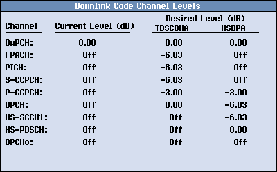
You can set the downlink DPCH Level. The power levels of other channels are fixed in the test set, as shown in the Downlink Code Channel Levels Screen.
DPCH Level - This setting allows you to set the DPCH power level from -30 to 0 dB. You can also turn off the DPCH power state, in which case the UE will not be able to detect the downlink DPCH.
The Downlink Code Channel Power Level screen displays the downlink channel levels currently in use by the test set (known as the "current" values), as well as the "desired" levels (including DPCHo). To query the results using GPIB commands, see CALL:STATus.

The DPCHo Level is a calculated value used to balance the relative power levels in a time slot so that they sum to 100% of the cell power. The Current DPCHo Level indicates the current power level in use and the Desired Level indicates the calculated level. When DPCH Level is changed, the test set re-calculates a DPCHo level in order that the DPCH and DPCHo levels sum to 100% of the cell power. If the state of DPCH Level is set to Off, the downlink DPCH channel can not be detected by the UE and the DPCHo occupies 100% of the time slot power.
The DPCHo is always active concurrently with the DPCH.
The test set supports downlink closed loop power control if an RB test mode call connection is set up in Active Cell operating mode. In response to the TPC (Transmit Power Control) bits from the UE, the test set adjusts the downlink DPCH power accordingly. Downlink power control helps to test the ability of the UE receiver to converge to required link quality set by the network while using as low power as possible in downlink.
For an ordinary transmit power control procedure, the UE generates TPC commands, and sends a unique TPC command in each slot to control the network transmit power (referred to as downlink power control mode 0 (DPC_MODE = 0) in the 3GPP standard). The DPC_MODE parameter is a UE specific parameter and fixed to "0" in the test set. Downlink closed loop power control is applicable when Channel Type is 12.2k RMC SC, 12.2k RMC MC or 64k RMC.
When Downlink Power Control Parms (F1) is pressed, the following parameters are displayed in the Downlink Power Control Parameters middle menu:
This parameter allows you to enable or disable downlink closed loop power control. This parameter can only be set when the Call Status is Idle.
GPIB Command: CALL[:CELL]:CLPControl:DOWNlink:STATe
Sets the maximum DPCH power offset. DPCH power offset sets the relative DPCH slot power level to the Cell Power. This setting can be changed under connection state in Active Cell operating mode when Downlink Closed Loop Power Control State is set to On.
GPIB Command: CALL[:CELL]:CLPControl:DOWNlink:DPCHannel:LEVel:MAXimum
Sets the minimum DPCH power offset. DPCH power offset sets the relative DPCH slot power level to the Cell Power. This setting can be changed under idle state in Active Cell operating mode or Downlink Closed Loop Power Control State is set to Off.
GPIB Command: CALL[:CELL]:CLPControl:DOWNlink:DPCHannel:LEVel:MINimum
Sets the quality target (BLER target) on DTCH. This setting can only be changed when Call Status is Idle or Downlink Closed Loop Power Control State is set to Off.
GPIB Command: CALL[:CELL]:CLPControl:DOWNlink:DTCHannel:TARGet:QUALity,CALL[:CELL]:CLPControl:DOWNlink:DTCHannel:TARGet:QUALity:STATe
Sets how many DPCH power offset sequence to be recorded each time the Start Record DPCH Level action is performed.
GPIB Command: CALL[:CELL]:CLPControl:DOWNlink:DPCHannel:LEVel:RECord:COUNt
This action starts/aborts the recording of DPCH power offset sequence. The number of the downlink power control information to record is specified by DPCH Level Sequence Record Count.
GPIB Command: CALL[:CELL]:CLPControl:DOWNlink:DPCHannel:LEVel:RECord:STARt, CALL[:CELL]:CLPControl:DOWNlink:DPCHannel:LEVel:RECord:STOP