The Handover function implemented in the E6651A operates through MAC messages between the BS and SS. Hence it is accessed via the Protocol FN Test menu in BS Emulator mode. Two E6651A Test Sets are required to perform handover testing of the Subscriber Station.
The Handover menu has 4 lower level sub-menus. Press Mode, BS Emulator, Protocol FN Test for access. Click here to view the Handover menu structure. Each softkey label in the diagram is linked to its description in the Handover Menu Keys table. The Setting Menu is used to configure values for the MOB_NBR-ADV message, MOB_SCN-RSP message, MOB_BSHO-REQ message, and the DCD message.
|
|
|
|
|
|
|
|
|
|
|
|
|
|
|
|
|
| |
|
|
|
|
|
|
|
|
|
|
|
|
|
| |||||
|
|
|
|
|
|
|
|
|
|
|
| |||||||
|
|
|
|
|
|
|
|
|
|
|
|
| ||||||
|
|
|
|
|
|
|
|
|
|
|
|
|
|
|
| |||
|
|
|
|
|
|
|
|
|
|
|
|
|
|
|
||||
|
|
|
|
|
|
|
|
|
|
|
|
|
|
|
||||
|
|
|
|
|
|
|
|
|
|
|
|
|
|
|
|
|||
|
|
|
|
|
|
|
|
|
|
|
|
|
||||||
|
|
|
|
|
|
|
|
|
|
|
|
|
||||||
|
|
|
|
|
|
|
|
|
|
|
|
|
|
|
|
|||
|
|
|
|
|
|
|
|
|
|
|
Neighbor #1 |
|
||||||
|
|
|
|
|
|
|
|
|
|
|
|
|
Neighbor #2 |
|
| |||
|
|
|
|
|
|
|
|
|
|
|
|
Neighbor #3 |
|
| ||||
|
|
|
|
|
|
|
|
|
|
|
|
|
|
|
|
| ||
|
|
|
|
|
|
|
|
|
|
|
|
|
|
|
|
| ||
|
|
|
|
|
|
|
|
|
|
|
|
|
|
|
|
| ||
|
|
|
|
|
|
|
|
|
|
|
|
|
| |||||
|
|
|
|
|
|
|
|
|
|
|
||||||||
|
|
|
|
|
|
|
|
|
|
|
|
|
| |||||
Press Mode, BS Emulator, Protocol FN Test, Handover, MOB_NBR-ADV msg. and select [ON] to periodically send the MOB_NBR-ADV message to the SS.
Press Mode, BS Emulator, Protocol FN Test, Handover, MOB_SCN-RSP msg. to send an unsolicited MOB_SCN-RSP message to the SS.
Press Mode, BS Emulator, Protocol FN Test, Handover, MOB_BSHO-REQ msg. to initiate a handover from the BS.
Press Mode, BS Emulator, Protocol FN Test, Handover, DCD msg. and select Apply to set the updated trigger values in the DCD message which is sent to the SS every 4 seconds.
The Handover topic contains the following sections:
Connect the Test Equipment and MS as shown below using a combining device such as an Agilent 11667A Power Splitter. BNC cables are required to connect the Test Sets' 10 MHz References and trigger output/inputs as shown.
Configure the Serving BS as follows:
Indicate to the SS that the BS supports Handover by pressing Mode, BS Emulator, Settings, BSE Setting, More, More, More, More, Mobility Negotiation, and Handover Support to select [ON].
Connect to the SS by performing the Network Entry procedure.
Press Mode,
BS Emulator, Protocol
FN Test, Handover,
Setting, MOB_NBR-ADV
msg, Neighbor #1,
Neighbor #2, Neighbor
#3 and set a unique BSID, Preamble Index, Frequency and Permutation
base for each neighbor enabled. By default, Neighbor #1 is enabled, Neighbor
#2 and #3 are disabled.
An example of setting up 3 neighbors is provided below:
|
|
Neighbor #1 |
Neighbor #2 |
Neighbor #3 |
|
BSID |
0x010101 |
0x010102 |
0x010103 |
|
Preamble Index |
33 |
66 |
99 |
|
Frequency |
2.501 |
2.593 |
2.685 |
|
Permutation Base |
3 |
4 |
5 |
To advertise the neighbor information to the SS, press Mode, BS Emulator, Protocol FN Test, Handover, and MOB_NBR-ADV msg. to select [ON].
Configure the Target BS as follows:
Press Mode, BS Emulator, Settings, BSE Setting and
set the Preamble, UL Permbase and BSID equal to one of the neighbors as
defined in the MOB_NBR-ADV message from the Serving BS (refer to step
3 of Setup the Serving BS). An
example is provided below:
|
Neighbor #1 |
|
|
Preamble |
33 |
|
UL Permbase |
3 |
|
BSID |
0x010203010101 |
|
Frequency |
2.501 (Press Frequency, Center) |
Press System and select Clock Source [Ext]. Check that the reference indicator on the screen of the E6651A changes to "EXT". If "EXT" is shown in red, the E6651A is not able to lock to the external reference and the interconnect cabling should be checked.
Press System, Ext. Trigger and Use Input Trigger to select [ON].
Un-pause Target BS.
If the example trigger settings have been used, the DUT initiates scanning and sends a MOB_SCN-REQ to the BS. The DUT completes handover after further message exchanges with the BS.
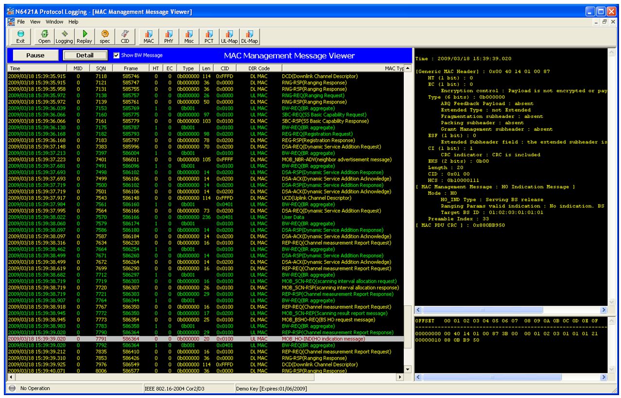
Using the N6421A Protocol Logging Application, you can observe the following protocol message sequence when logging the Serving BS:
SS sends MOB_SCN-REQ message to BS.
BS sends MOB_SCN-RSP message to SS.
SS sends MOB_SCN-REP message to BS.
BS sends MOB_BSHO-REQ
message to SS.
If Auto Send [ON] (BS Emulator
, Protocol FN Test , Handover , Setting
, MOB_BSHO-REQ msg. ,
Auto
Send ON/OFF), the BS sends MOB_BSHO-REQ in response to the MOB_SCN-REP
from the SS. If
Auto Send [OFF], the SS may send a MOB_MSHO-REQ message to initiate a
handover.
SS sends MOB_HO-IND message to BS.
An example of the message sequence:
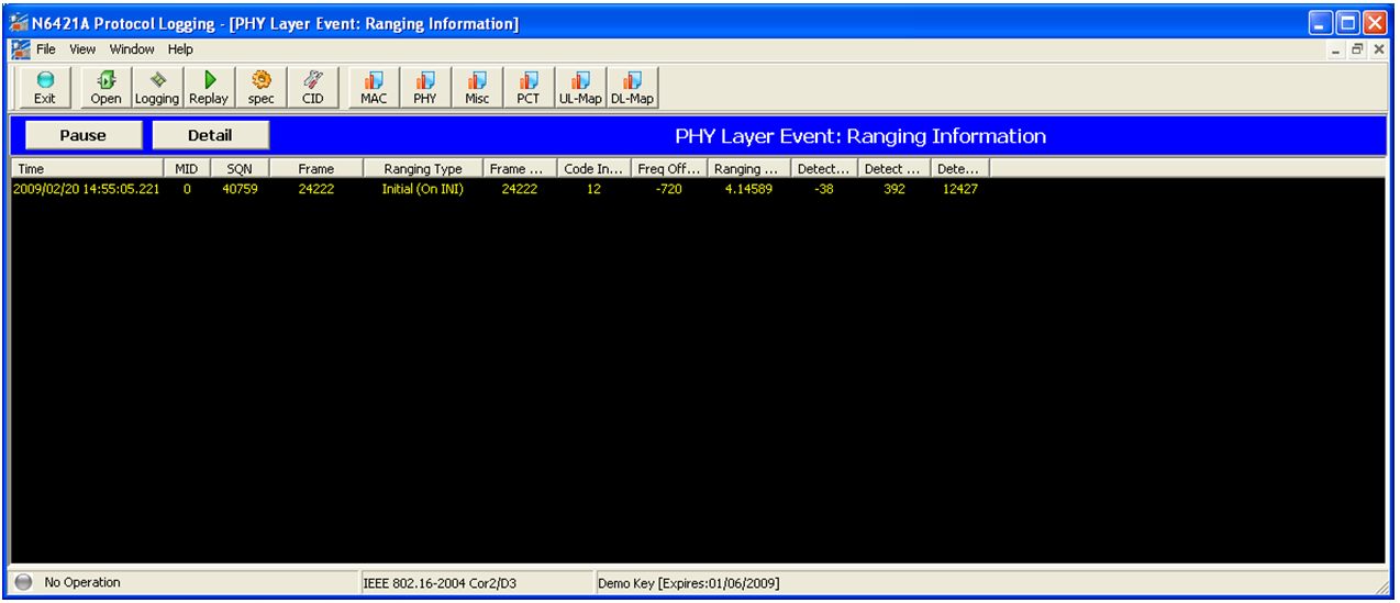
You can observe an Initial Ranging Code of 12 when logging the Target BS:
In the Subscriber Station Information window of the Target BS, you will observe the Connection state and this completes the handover to the Target BS.
Setup Event Trigger Conditions
On the Serving BS, the SS trigger information can be setup in the DCD msg. menu (Mode, BS Emulator, Protocol FN Test, Handover, Setting, DCD msg). It is possible to set up 2 trigger conditions.
An example of setting up an Event Trigger Condition:
Select the trigger type using the Trig. Type setting. The options available are [CINR Metric], [RSSI Metric] and [RTD Metric]. For example, select the [RSSI Metric].
Define the trigger condition using the Trig. Function and Trig. Value settings. For example, set the Trig. Function to [Serving < Value] and the Trig. Value to -60dBm. When the RSSI of the Serving BS falls below -60dBm, the trigger condition is met.
Select the required trigger
action using the Trig. Action
setting. This
is the action that the SS will perform when the trigger condition is met.
For example,
select [Initiate Scanning]
The E6651A supports the following SS trigger actions as defined in
the IEEE Std 802.16 Table 358b:
[Initiate Scanning] - On trigger, MS starts the neighbour BS scanning process by sending MOB_SCN-REQ
[Perform Scanning] - On trigger, MS should perform scanning
[Send MOB_SCN-REP] - Respond on trigger with MOB_SCN-REP after the end of each scanning interval
[Send MOB_MSHO-REQ] - Respond on trigger with MOB_MSHO-REQ
Press Apply to set the updated trigger values in the DCD message. This is sent to the SS every 4 seconds.
To activate the trigger in the example above, press Amplitude, Source Amplitude and use the knob or down arrow key to decrease the power level value in small increments to below -60dBm
Second DCD Trigger can be set to "Off".
|
Softkey |
Description |
Default |
API Command |
|
Press Apply to update the trigger values in the DCD message. This is sent to the SS every 4 seconds. |
X |
||
|
Press BSID to set the Neighbor BSID. This will be applied in the MOB_NBR-ADV message. |
Neighbor #1 = 0x010101 |
||
|
Press Config. CC to set the Configuration Change Count value of the MOB_NBR-ADV message. |
0 |
||
|
Press DCD Config CC to set the Neighbor DCD Configuration Change Count value. The value can be found using the N6421A Protocol Logging application to log the neighbor DCD message. |
0 |
||
|
Press DCD msg. to access the configuration menu. |
X |
None | |
|
Press Frequency to set the Neighbor Frequency. This will be applied in the MOB_NBR-ADV message. |
2.345 |
||
|
Press Interleaving Interval to set the interleaving interval value in the MOB_SCN-RSP message. |
100 |
||
|
Press MOB_BSHO-REQ msg. to indicate a handover from the BS. |
X |
||
|
Press MOB_BSHO-REQ msg. to input the Target BSID for the handover. |
X |
None | |
|
Press MOB_NBR-ADV msg. to switch the MOB_NBR-ADV message on or off and to set the rate. The message is sent to the SS in frames. |
Off |
Get/Set_BSHOMOB_NBR_ADVEnable and Get_Set_BSHOMOB_NBR_ADVRate | |
|
Press MOB_NBR-ADV msg. to access the configuration menu. |
X |
None | |
|
Press MOB_SCN-RSP msg. to send an unsolicited MOB_SCN-RSP message to the SS with the configured settings. |
X |
||
|
Press MOB_SCN-RSP msg. to access the configuration menu. |
X |
None | |
|
Press Neighbor #1 to access the configuration menu. |
X |
None | |
|
Press Neighbor #2 to access the configuration menu. |
X |
None | |
|
Press Neighbor #3 to access the configuration menu. |
X |
None | |
|
The Operator ID can only be modified using the API command. |
0x010203 |
||
|
Press Permutation Base to set the Neighbor Permutation Base value. This will be applied in the MOB_NBR-ADV message. |
17 |
||
|
Press PHY Profile ID to set the PHY Profile ID value. This will be applied in the MOB_NBR-ADV message. |
96 |
||
|
Press Preamble Index to set the preamble index of neighbor BS. Range 0 to 113 |
0 |
||
|
Press Report Mode to set the reporting mode in the MOB_SCN-RSP message. Options are No Report, Periodic, or Event Triggered. |
Periodic |
||
|
Press Report Metric to set the metric on which the handover trigger condition is based. This is set in the MOB_SCN-RSP message. |
CINR |
||
|
Press Report Period to set the report period value (in frames) in the MOB_SCN-RSP message. This is only available when the Report Mode is set to Periodic. |
50 |
||
|
Press Scan Duration to set the scan duration value (in frames) in the MOB_SCN-RSP message. |
200 |
||
|
Press Scan Iteration to set the scan iteration value in the MOB_SCN-RSP message. |
200 |
||
|
Press Scanning Type to select the Scanning Type for each neighbor. Options are Without Association or Association Level 0. |
Without Association |
||
|
Press Setting to access MOB_NBR-ADV, MOB_SCN-RSP, MOB_BSHO-REQ, and DCD message configuration menus. |
X |
None | |
|
Press Start Frame to set the start frame value in the MOB_SCN-RSP message. |
1 |
||
|
Press Target BSID to specify the target Base Station ID value in the MOB_BSHO_REQ msg. |
Neighbor #1 (0x010203010101) |
||
|
Press Trig. Type to set the trigger type to CINR Metric, RSSI Metric, or RTD Metric for the DCD message. |
CINR Metric |
||
|
Press Trig. Function to set the trigger function for the DCD message. |
Serving < Value |
||
|
Press Trig. Action to set the trigger action for the DCD message. This is the action the S will perform when the trigger condition is met. Options are Initiate Scanning, Perform Scanning, Send MOB_SCN-REP and Send MOB_MSHO-REQ. |
Initiate Scanning |
||
|
Press Trig. Value to set the trigger value for the DCD message. This value is used in the Trigger Function. |
25 |
||
|
Press Trig Aver. Duration to set the trigger average duration for the DCD message. |
128 |
||
|
Press UCD Config CC to set the Neighbor UCD Configuration Change Count value. |
0 |