How Do I Use R-FCH Gating for Talk Time Testing?
Last updated: October 28, 2004
This section is only applicable to the lab application.
A method for testing mobile station's talk time is proposed by the test 2.1 of the CDG Stage 4 test standard (CDG 35). This test measures talk time of a mobile station by exhausting its fully charged battery in a long loopback call to the base station. The test procedure employs loopback and relies on simulating the typical 40% voice activity (see also Traffic Data Rate ).
Test Procedure
- Fully charge the mobile station battery using its normal charger. Ensure the mobile station's back lighting is disabled or set to the minimum. Do not attach the diagnostic monitor during the test. Ensure the mobile station is in an environment with a stabilized ambient temperature of 25°C.
- Connect the mobile station to the test set's front panel RF IN/OUT connector.
- Connect an external PC to the test set.
- Set up the test set with the following parameters (see also How Do I Change Call Parameters? ):
- Press CALL SETUP . The Call Parms and Call Control menus are displayed on both sides of the screen.
- Set
System Type( F2 ) to IS-2000. - Set
Radio Config( F11 on theCall Parms 1 of 4) to(Fwd3, Rvs3). - Select FCH Service Option Setup ( F12 )
(Call Parms 1 of 4), setService Option for Fwd3, Rvs3toSO2 (Loopback). (varies the setting according to your mobile station) - Set the
Traffic Data Rate( F12 on theCall Parms 2 of 4) toRandom (40% Voice Activity). See Traffic Data Rate . - Set the
R-FCH Gating( F7 on theCall Parms 3 of 4) toOn. See R-FCH Gating . - Set
Cell Power(( F7 on theCall Parms 1 of 4) to-75 dBm/1.23 MHz. - Set the
F-Pilot Levelto -7.00 dB, and set theF-FCH/Traffic Levelto -15 dB (see How Do I Change Generator Information? ).
- Page the MS by pressing the
Originate Call( F3 ). Verify that theConnectedActive Cell status - Have the external software running on the PC to control the test, including:
- Start the talk time timer in the external software to measure call duration.
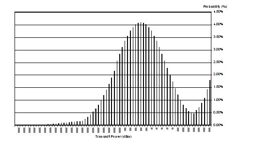
- Have the external software automatically change the cell power of the test set such that the mobile station is controlled to a specific transmit power profile as specified in the standard (see Mobile Station Transmit Power Statistics (Preliminary )(Suburban Topography) for an example profile of suburban topology). Power control should occur as follows:
- Control the mobile station transmit power at 0 dBm.
- The mobile station's transmit power will have a nominal dwell time of 2 seconds per each percent of probability. For example, if probability is 3.00% then the dwell time shall be 6.00 seconds.
- At the end of each dwell time, control the mobile station at the next higher transmit power level.
- Once the mobile station power has reached maximum power (typical is 23 dBm), control the mobile station to dwell at that power level twice.
- Control the mobile station to decrement the transmit power in an analogous fashion until the minimum power level of -50 dBm is reached.
- When the minimum mobile station power is reached, control the mobile station to dwell at that power level twice.
- Have the external software continue by alternately increasing and decreasing mobile station transmit power.
- Continue the call until the MS's battery is exhausted and the call is dropped.
- Stop the talk time timer in the external software and record the call duration.
Minimum Standard: Measured talk-time for the mobile station shall be recorded along with data on the type and nominal capacity of the battery used. Data obtained in this test provides the expected talk time in realistic field conditions. Real talk times experienced in the field may vary due to factors such as talk patterns and actual CDMA signal conditions.
| -3 | -28 | ||||
| -14 | -39 | ||||
| -17 | -42 | ||||
| -18 | -43 | ||||
| -22 | -47 | ||||
The average mobile station power from the above profile is 11.5 mW (10.6 dBm).
|
|
