Time Response of Open Loop Power Control (TROLPC) Measurement Description
Last updated: October 28, 2004
- How is a TROLPC measurement made?
- TROLPC Measurement Parameters
- TROLPC Measurement Results
- Input Signal Requirements
- Key TIA/EIA-98-E Tests Using the TROLPC Measurement
- Calibrating the TROLPC Measurement
How is a TROLPC measurement made?
The TROLPC measurement is a power versus time measurement that analyzes the output power of a mobile station for the 100 ms period following an abrupt (step) change (+/- 20 dB) in output power from the test set.
This measurement is made while the mobile station is in a loopback connection at full data rate transmission (see Operating Considerations ).
When you initiate the test set's TROLPC measurement, cell power either increases or decreases by 20 dB depending upon whether you initiate an up or down step change. When the cell power changes, the mobile station reacts by decreasing or increasing its power, according to the open loop equation. The test set automatically sends alternating up and down closed loop power control bits while the measurement is executing (that is, the the Rvs Power Ctrl (reverse power control) mode is temporarily set to Alternating (up/down) bits), so the mobile station's response is determined solely by the open loop equation, and not influenced by closed loop power control. (On the TROLPC graph, the alternating power control bits appear only as "ripple" on the measured trace.)
Two softkey selections are provided for triggering TROLPC measurements:
- Start Meas Up (increases power from the test set)
- Start Meas Down (decreases power from the test set).
When the F2 ( Start Meas Up ) or F3 ( Start Meas Down ) softkey is selected, the Cell Power ( F7 ) setting will automatically step up or down 20 dB. The START SINGLE hardkey will also begin a TROLPC measurement, defaulting to the last measurement choice of stepping up or down 20 dB.
As soon as the new cell power level is received by the mobile station, the test set begins measuring the mobile station output power and continues to measure power for the 100 ms period following the change in cell power . The test set measures power at 371 data points over the 100 ms following the step change in cell power. The test set will automatically range its measuring receiver to the expected value from the mobile station as the test is performed.
After the TROLPC measurement has completed, the test set returns closed loop power control to the mode it was set to before the measurement was initiated.
TROLPC test results include a pass/fail indication determined by the mobile station's conformance to test standard amplitude mask limits. If a TROLPC test fails, the display will show the first point that the trace crossed the amplitude mask. See TROLPC Measurement Results )
TROLPC Measurement Parameters
- F-FCH/Traffic Level - (see Configuring the Forward Fundamental/Traffic Channel (F-FCH/Traffic) ).
- Timeout Time/State - (see Timeouts ).
TROLPC Measurement Results
- Integrity Indicator - (see Integrity Indicator ).
- The TROLPC Measurement Screen
- Pass/Fail Limits (Amplitude Mask)
The TROLPC Measurement Screen
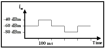
By standard definition the TROLPC test process consists of a series of measurements. Before these measurements are made, the Cell Power parameter is set to -60 dBm/1.23 MHz. Then, to test the mobile station over the operating range of interest, the following sequence of tests is performed:
- Start Meas Up (Cell Power transitions to -40 dBm/1.23 MHz)
- Start Meas Down (Cell Power transitions to -60 dBm/1.23 MHz)
- Start Meas Down (Cell Power transitions to -80 dBm/1.23 MHz)
- Start Meas Up (Cell Power transitions to -60 dBm/1.23 MHz)

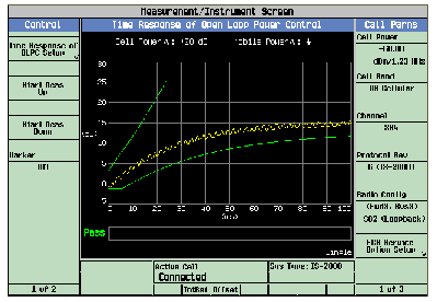
Refer to Time Response of Open Loop Power Control for an example of the display after performing step 1 from the sequence above.
- The y-axis on the graphical display is fixed from -5 to 30 dB. There are no polarity indicators on the y-axis in accordance with the test standard specifications. All changes in mobile station output power are displayed as absolute values.
- The x-axis on the graphical display is fixed from 0 ms to 100 ms.
- The directions of Cell Power and mobile power level changes are displayed in text above the grid.
- The amplitude mask is displayed as green lines on the display.
- A marker is provided to display measurement levels across the 100 ms time interval.
- An overall pass/fail indicator is displayed and is available via GPIB commands (see FETCh:TROPower ). If a TROLPC test fails, the display will show the first point that the trace crossed the amplitude mask
- No statistical (multi-measurement) results are provided for this measurement.
Pass/Fail Limits (Amplitude Mask)
Pass/Fail limits are determined by comparing the mobile station response with an amplitude mask derived from the test standard TIA/EIA IS-98D, 4.4.2 Time Response of Open Loop Power Control. When analyzing the results of time response to open loop power control programmatically, a comparison between the trace (see FETCh:TROPower:TRACe? ) and the mask can be made using the following formula:
For computing the upper pass/fail limit line:
The upper pass/fail limit line is made up of three line segments. In the following formulas, p is mobile station power delta, in dB, and t is equal to time in milliseconds. Note: These formulas are derived from test standard TIA-EIA IS-98D and apply to a cell power step size of 20 dB only.
For computing the lower pass/fail limit line:
The lower pass/fail limit line is made up of one line segment and a curve. In the following formulas, let t1 equal:
Input Signal Requirements
The TROLP measurement meets or exceeds specifications when the following requirements are met:
- The frequency of the signal being measured must be in the range of 412 MHz to 483 MHz, 800 MHz to 960 MHz, or 1.7 GHz to 2.0 GHz, and within 100 kHz of the expected frequency.
- The signal level into the test set's RF IN/OUT connector must be in the range of -25 dBm to +37 dBm, and within 9 dBm of the expected input power (see RFANalyzer:AUTO:POWer[:SELected]? ) to meet specifications.
Calibrating the TROLPC Measurement
The TROLPC measurement is automatically calibrated during a channel power calibration. Follow the channel power calibration schedule and the TROLPC measurement will be properly calibrated. Refer to Calibrating the Test Set for a description of channel power calibration.
Related Topics
|
|
Measuring Time Response of Open Loop Power Control (TROLPC)
Programming a TROLP Measurement
Time Response of Open Loop Power Control (TROLPC) Troubleshooting
|
|


