Transmit Power Measurement Description
Last updated: November 25, 2010
The Transmit Power Measurement is applicable to GSM/GPRS/EGPRS lab application and a test application with the required feature license. The EGPRS Transmit Power Measurement is applicable to the EGPRS lab application and test application
Transmit Power (TXP) Measurement
How is a TXP measurement made?
TXP measurement provides the Burst Power and Estimated Carrier Power measurements for GMSK, 8PSK or 16QAM modulated signals. You can use Burst Capture Range to configure whether a single uplink burst or all uplink bursts in one TDMA frame are measured during the TXP measurement.
-
TXP Measurement with
Burst Capture Range
set to
SingleWhen Burst Capture Range is set to
Single, the TXP measurement measures the Burst Power of a single burst (GMSK modulated) at one capture of the TDMA frame, the TXP measurement supports the multislot configuration of up to 2 uplink bursts, but only the burst specified by the Measurement Burst parameter is measured each time.In EGPRS Active Cell and Test modes, An `Unsupported Configuration' message is displayed when using the TXP Measurement with Burst Capture Range set to
Single. You should use the EGPRS Transmit Power (ETXP) Measurement instead.In order to provide you with a very fast TXP measurement the test set measures the power without synchronizing it to the midamble. The measurement is made with RF amplitude synchronization; therefore, the signal does not need to be demodulated to determine the midamble. This technique is different from the TXP measurement defined in 3GPP 51.010 (formerly ETSI GSM 11.10). (See Burst Synchronization of Measurements ). The power versus time measurement provides a carrier power measurement that is synchronized to the burst's midamble, and conforms to 3GPP 51.010 (formerly ETSI GSM 11.10), section 13.3 and 3GPP 51.010 (formerly ETSI GSM 11.10), section 13.16.2. (See Power versus Time Measurement Description for more details.)
The TXP measurement can be made on the following types of input signals:
-
TXP Measurement with
Burst Capture Range
set to
AllWhen Burst Capture Range is set to
All, the TXP measurement measures the Burst Power and Estimated Carrier Power of all uplink bursts (either 8PSK or GMSK modulated) at one capture of the TDMA frame. The TXP Measurement can measure both consecutive and non-consecutive uplink bursts depending on the uplink burst configuration state setting:- When the uplink burst configuration state is set to OFF, the TXP measurement supports the multislot configuration of up to 6 consecutive uplink bursts in all operating modes.
- When the uplink burst configuration state is set to ON, the TXP measurement supports the uplink burst configuration of up to 7 non-consecutive uplink bursts in GPRS BCH+PDTCH or EGPRS BCH+PDTCH operation mode. The multislot configuration does not work when the uplink burst configuration state is set to ON, you should use the uplink burst configuration instead. See PDTCH Parameters to see more information about the uplink burst configuration. The Burst Capture Range is set to all and can not be changed in this senario.
The Burst Power measurement results (with averaging turned on) conform to ETSI GSM 05.05 (Ver 8), section 4. It also conforms with 3GPP 51.010 (formerly ETSI GSM 11.10) if used as part of a type approval system. The Estimated Carrier Power measurement results meet the accuracy requirements for an estimation technique of long term average power as defined in 3GPP 51.010, annex 5.
The TXP measurement can be made on these types of input signals.
See the following table for instructions on how to properly set the Burst Capture Range and how to select the correct measurement.
| GSM/GPRS Active Cell and Test Modes | EGPRS Active Cell and Test Modes | CW Operating Mode | |
|---|---|---|---|
| Single burst | "TXP Measurement with "Burst Capture Range" set to Single" . | EGPRS Transmit Power (ETXP) Measurement . | "TXP Measurement with "Burst Capture Range" set to Single" . |
| Multiple bursts | "TXP Measurement with "Burst Capture Range" set to All" . | Not applicable. | |
The TXP measurement is completely controlled by the test set. The power meter used for this measurement is zeroed automatically by the DSP as needed. No temperature dependent calibration is required because temperature compensation in the power detector circuits provide temperature stability.
Operating Consideration
The following table lists the behavior differences for different Burst Capture Range and uplink burst configuration settings.
| TXP Measurement with Burst Capture Range set to Single | TXP Measurement with Burst Capture Range set to All and Uplink Burst Configuration State set to OFF | TXP Measurement with Burst Capture Range set to All and Uplink Burst Configuration State set to ON | |
|---|---|---|---|
| Supported multislot classes | D1U1,D2U1,D3U1,D4U1,D5U1,D6U1, D1U2,D2U2,D3U2,D4U2, D5U2 | D1U1,D2U1,D3U1,D4U1,D5U1,D6U1,D1U2,D2U2,D3U2,D4U2,D5U2,D1U3,D2U3,D3U3,D4U3,D1U4,D2U4,D3U4,D1U5,D2U5,D1U6. | up to 7 non-consecutive uplink bursts... |
| Supported operating modes |
All operating modes except
Active Cell (EGPRS), EGPRS BCH+PDTCH
and
EGPRS BCH+TCH+PDTCH
. |
All operating modes. | GPRS BCH+PDTCH and EGPRS BCH+PDTCH. |
| Supported modulation formats | GMSK | GMSK, 8PSK, 16QAM | GMSK, 8PSK, 16QAM |
| Uplink burst number checking | No | Yes | Yes |
| Modulation format checking | No | Yes | No |
| Synchronization method | RF Amplitude | Midamble Sync (the test set automatically passes the Training Sequence Code (TSC) to the measurement with no action required by you. However, you must specify the TSC manually in the test mode.) | Fixed Offset |
| CW signal supported | Yes | No | No |
- You must set the measurement frequency and expected power correctly in order to get the accurate power result of the measured burst when measuring the non-consecutive bursts.
- When measuring the non-consecutive bursts, the first burst in each TDMA frame is assumed as the highest burst.
- When measuring the non-consecutive bursts, the mobile station is required to query whether the hardware of the test set has been armed to accept the input RF signal before transmission. The GPIB command to query the arm state of the test set in the non-consecutive measurement state is INITiate:TXPower:BMEasure:ARMed? .
- The uplink burst configuration is only available when the operating mode is set to GPRS BCH+PDTCH or EGPRS BCH+PDTCH.
Impact on Other Measurements
The TXP measurement can operate concurrently with other measurements when the Burst Capture Range is set to Single or when the Burst Capture Range is set to All and the uplink burst configuration state is set to OFF. However, when the uplink burst configuration state is set to ON, initiating the TXP measurement will cause other running measurements to be closed.
TXP Measurement Parameters
-
Arm State
This parameter is only applicable when the uplink burst state is set to ON. The parameter indicates whether the hardware of the test set has been armed to accept input RF signal.
The GPIB command to query this parameter is INITiate:TXPower:BMEasure:ARMed? .
-
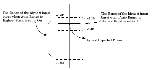
Auto Range to Highest Burst
This parameter is only applicable when Burst Capture Range is set to
All.Note, when Burst Capture Range is set to
All, you only need to set the expected power for the highest burst, which is called `highest expected power' in the following descriptions. see Expected Power Control for information on how to set the expected power.This parameter determines whether the test set ranges its hardware to the highest power of the input bursts or not. If this parameter set to
On, the test set ranges its hardware to the highest input burst before the measurement is performed. The specified accuracy can be achieved when the highest input burst is within the range of -30 dB to +3 dB relative to the highest expected power. If this parameter is set toOff, the test set ranges its hardware according to the highest expected power, but the highest input burst must be within the range of -3 dB to +3 dB relative to the highest expected power to achieve the specified accuracy. The figure below illustrates the ranges of the input burst which can achieve the specified accuracy based on the Auto-Ranging to Highest Burst setting.Note that the measurement speed will slow down when the Auto Range to Highest Burst parameter is set to
ON.The GPIB command to set this parameter is SETup:TXPower:RANGe:AUTO .
-
Burst Capture Range
This parameter determines whether a single uplink burst or all uplink bursts in a multi-slot configuration are measured during the TXP measurement. The default value for this parameter is
Single. When Burst Capture Range is set toSingle, the TXP measurement measures one burst which is specified by Measurement Burst . When Burst Capture Range is set toALL, the TXP measurement measures all bursts in one TDMA frame.The Burst Capture Range is not available when the Uplink Burst Configuration state is set to ON.
The GPIB command to set this parameter is SETup:TXPower:BURSt:CAPTure .
-
Estimated Carrier Power
This parameter is only applicable when Burst Capture Range is set to
Alland the operating mode isActive Cell (EGPRS), EGPRS BCH, EGPRS BCH+PDTCHorEGPRS BCH+TCH+PDTCH.This parameter specifies whether the Carrier Power is calculated. The default value for this parameter is
OnThe table below lists the relationship between Estimated Carrier Power State and the Estimated Carrier Power result displayed on front panel or retrieved by GPIB command.
The Estimated Carrier Power is not available when the Uplink Burst Configuration state is set to ON.
The GPIB command to set this parameter is SETup:TXPower:ECPower:STATe .
-
Frame Qualification
This parameter is only applicable when Burst Capture Range is set to
All.This parameter is used to determine whether the number of the measured bursts and their modulation formats are correct. When Measurement Frame Qualification is set to
On, the measurement checks the number of the measured bursts in a TDMA frame and the modulation format of the input signal. If they don't match the expected value, the samples are discarded and the samplers are re-armed.The Frame Qualification is not available when the Uplink Burst Configuration state is set to ON.
The GPIB command to set this parameter is SETup:TXPower:FRAMe:QUALifier .
-
Measurement Burst
This parameter indicates which burst in the multislot configuration is measured if the user chooses to measure an individual burst by setting Burst Capture Range to
SINGle. Measurement Burst is fixed to 1 when only a single uplink timeslot is present. See How Do I Configure the PDTCH Parameters? .The GPIB command to set this parameter is CALL:(PDTCH|PDTChannel):MSLot:MEASurement:BURSt .
-
Measurement Timeout
You can set the timeout state and time for this measurement. To set them separately, use SETup:TXPower:TIMeout:STATe to set the timeout state, SETup:TXPower:TIMeout:TIME to set the timeout time; use SETup:TXPower:TIMeout[:STIMe] to set the state and time simultaneously.
-
Multi-measurement Count
You can set Multi-Measurement state and count for the TXP measurement. If Multi-Measurement State is
On, Multi-Measurement Count determines how many measurements are to be performed for a measurement request. If Multi-Measurement State isOff, no Multi-Measurement are performed.The TXP measurement use the standard Multi-Measurement implementation. Each Multi-Measurement returns the average value, maximum value, minimum value and standard deviation for the number of counts selected. No intermediate results are returned during a Multi-Measurement.
Multi-Measurement count specifies how many loops are measured for a measurement request.
To set Multi-Measurement state and count separately, use SETup:TXPower:COUNt:STATe to set the Multi-Measurement state, SETup:TXPower:COUNt:NUMBer to set the Multi-Measurement count; use SETup:TXPower:COUNt[:SNUMber] to set the state and count simultaneously.
-
Multi-measurement Count Progress Indicator
There is a progress indicator displayed on the front panel that shows how many measurements of the total Multi-Measurement count have been made. You can retrieve it using FETCh:TXPower:ICOunt? .
-
Trigger Arm
Trigger arm can be set to
SingleorContinuous, See Trigger Arm (Single or Continuous) Description for more information.Note, during non-consecutive burst measuring with Uplink Burst Configuration State setting to ON, the trigger arm is set to
Singleand can not be changed.The GPIB command to set this parameter is SETup:TXPower:CONTinuous .
-
Trigger Delay
This is the specified time between the trigger event and when the test set begins sampling data. See Trigger Delay Description for more information.
The GPIB command to set this parameter is SETup:TXPower:TRIGger:DELay .
-
Trigger Qualification
This parameter defines whether the measurement will discard the samples on detection of an idle frame. If this parameter is set to
ON, the samples is discarded; If the parameter is set toOFF, the measurement continues to be completed.The GPIB command to set this parameter is SETup:TXPower:TRIGger:QUALifier .
-
Trigger Source
Auto triggering is the recommended trigger source for each measurement. This allows the test set to choose the preferred trigger source. See Trigger Source Description . The following table shows the recommended trigger source for the TXP measurement.
Note, When measuring the non-consecutive bursts, the trigger source will be fixed as RF Rising for the first acquisition of the measurement, then protocol trigger will be used for all the subsequent TDMA frames.
Recommended Trigger Source Operating mode Active Cell CW signal The GPIB command to set this parameter is SETup:TXPower:TRIGger:SOURce .
TXP Measurement Results
The results returned by the TXP measurement are Burst Power, Estimated Carrier Power and Integrity Indicator. Additionally, average, maximum, minimum and standard deviation of Burst Power and Estimated Carrier Power are returned when the Multi-Measurement state is
On
.
Burst Power and Estimated Carrier Power measurement results
The TXP measurement returns two types of power results:
-
Burst Power
This is the average power measured across a single timeslot. This value varies as a function of the modulating data.
-
Estimated Carrier Power
This is an estimate of the power of the unmodulated carrier. The Estimated Carrier Power is equivalent to the Long Term Average Power which is the primary definition of 8PSK or 16QAM modulated signal power in the ETSI standards. Long Term Average Power is the average power of many individual bursts when the individual bursts are modulated with PRBS data. The Estimated Carrier Power measurement uses knowledge of the modulating data to determine the carrier power from the power measurement.
When the modulation format of the measured burst is GMSK, Burst Power and Estimated Carrier Power results are equivalent.
When
Burst Capture Range
is set to
Single
, you can query the Burst Power and the Estimated Carrier Power for the burst specified by
Measurement Burst
. The Burst Power and Estimated Carrier Power are equivalent.
When
Burst Capture Range
is set to
All
, you can query the Burst Power and the Estimated Carrier Power for a specified burst or all bursts in one TDMA frame:
-
Query the measurement results for a specified burst
The FETCh commands may contain an optional parameter that is used to specify the burst. Measurement results of the burst specified by the optional parameter are returned. If you omit the optional parameter, measurement results of the burst specified by Measurement Burst are returned.
-
Query the measurement results for all bursts
The FETCh commands return the measurement results in the following order: <Result for Burst 1>, <Result for Burst 2>, <Result for Burst 3>, <Result for Burst 4>, <Result for Burst 5>, <Result for Burst 6>, <Result for Burst 7>, <Result for Burst 8>. Note that the results for the inactive bursts in the multislot configuration are not valid.
TXP Measurement Integrity Value
Integrity values provide information that allows you to judge how useful the result is. See Integrity Indicator .
TXP Measurement Input Signal Requirements
-
Single Burst Capture TXP Measurement
When Burst Capture Range is set to
Single, the TXP measurement will complete and be accurate when: -
Multiple Burst Capture TXP Measurement
When Burst Capture Range is set to
All, the TXP measurement will complete and be accurate when:- The input signal is within +/- 100 kHz of the expected frequency.
- The level of the input burst is between -25 dBm and +30 dBm when measureing the Burst Power of 8PSK modulated bursts.
- The level of the input burst is between -25 dBm and +33 dBm when measureing the Burst Power of 8PSK modulated bursts.
- The level of the input burst is between -25 dBm and +37 dBm when measuring the Burst Power of GMSK modulated bursts.
- The level of the input burst is between -20 dBm and +33 dBm when measuring Estimated Carrier Power.
-
When the Auto Range to Highest Burst parameter is set to
OFF: -
when the Auto Range to Highest Burst parameter is set to
ON:
EGPRS Transmit Power (ETXP) Measurement
The EGPRS Transmit Power (ETXP) Measurement is used when you want to measure a single 8PSK burst. otherwise you are suggested to use the GSM/GPRS/EGPRS Transmit Power (TXP) Measurement.
ETXP is applicable only when the operating mode parameter is set to Active Cell (EGPRS), EGPRS BCH, EGPRS BCH+PDTCH or EGPRS BCH+TCH+PDTCH.
How is an EGPRS transmit power (ETXP) measurement made?
For EGPRS mobiles, ETXP provides a broadband measurement of the average transmitted burst and carrier power of an 8PSK or GMSK modulated signal for a specified burst in a multislot configuration. Multislot configurations with different power levels on each burst are supported. Only one burst which you specify using CALL:(PDTCH|PDTChannel):MSLot:MEASurement:BURSt is measured at a time. You can also control the modulation and coding scheme (either 8PSK or GMSK modulation) used by the data connection to be measured using CALL:(PDTCH|PDTChannel):MCSCheme . Additionally, you can manually control what modulation should be expected for individual bursts using CALL:MODulation[:FORMat]:CONTrol:AUTO . See "Modulation Format Control (EGPRS only)" on page 10 for more information.
The EGPRS radio format allows for all GMSK, all 8PSK or a mixture of GMSK and 8PSK bursts in a multislot configuration. Additionally, when a timeslot supports an 8PSK packet data traffic channel (PDTCH), GMSK modulated control blocks can be inserted. When you specify a burst to measure, the measurement takes samples only from that burst in the multislot configuration. If the modulation is the same as the modulation and coding scheme you have selected or the modulation format you manually specified, the measurement proceeds normally. If the modulation is not the same, the samples are discarded and the measurement is re-armed. The measurement completes when a burst using the same modulation is detected.
Single or Multi-Measurements
The 8PSK Transmit Power measurement supports single Burst Power and Estimated Carrier Power measurements. For multi-burst measurements, the average value of Burst Power is equivalent to the Long Term Average Power defined in the ETSI standards. You can choose either a more accurate but slower measurement with the multi-measurement Burst Power result, or a less accurate but faster measurement with the Estimated Carrier Power result.
This measurement calculates average, minimum, maximum, and standard deviation values for the burst power and estimated carrier power results. When the measured signal's modulation format is GMSK, Burst Power and Carrier Power measurements are equivalent so both results return the same value. All of these results are available using the FETCh commands (see FETCh:ETXPower ). The test set always has an integrity indicator available regardless of whether single or multiple burst measurements are selected.
Types of Signals ETXP can Measure
The following list summarizes the input signal attributes and mobile station operating modes for making ETXP measurements.Normal GSM TCH burst with the operating mode set to active cell and the serving cell set to EGPRS.
- Two burst multislot configuration comprising two normal PDTCH bursts with the operating mode set to active cell and the serving cell set to EGPRS.
- Single normal PDTCH burst with the mobile station in active cell mode.
- Access (RACH) burst with the mobile station in active cell mode.
- Two burst multislot configuration comprising two normal PDTCH bursts with the mobile station in EGPRS BCH, EGPRS BCH+PDTCH or EGPRS BCH+TCH+PDTCH test mode (no protocol).
- Single normal PDTCH burst with the mobile station in EGPRS BCH, EGPRS BCH+PDTCH or EGPRS BCH+TCH+PDTCH test mode (no protocol).
- Access (RACH) burst with mobile station in EGPRS BCH, EGPRS BCH+PDTCH or EGPRS BCH+TCH+PDTCH test mode (no protocol).
Trigger Source
Auto triggering is the recommended trigger source for each measurement. This allows the test set to choose the preferred trigger source. However you may want to select the trigger source. See Recommended Trigger Source Settings