TX Spurious Emissions Measurement Description
Last updated: January 15, 2009
- How is a TX Spurious Emissions Measurement Made?
- TX Spurious Emissions Measurement Parameters
- TX Spurious Emissions Measurement Results
- TX Spurious Emissions Input Signal Requirements
- Key C.S0033 Tests Performed using the TX Spurious Emissions Measurement
- Calibrating the TX Spurious Emissions Measurement
How is a TX Spurious Emissions Measurement Made?
TX Spurious Emissions is a measure of the access terminal's transmission at frequencies outside its assigned channel.
TX Spurious Emissions measurement with a single test set
When performing with a single test set, the TX Spurious Emissions measurement is made by first making a channel power measurement centered on the assigned channel, to determine carrier power. The test set then measures the power at four frequencies offset from the center of the assigned channel. The test set measures the average power present at each frequency offset, over a slot, within a 30 kHz filter centered on the offset frequency. The test set then reports the power of each frequency offset relative to the carrier power (the result is given in dBc).
The four frequency offsets at which power is measured depends upon the AT band class:
- Frequency offsets for band classes 1, 4, 6,14 and 15:
- Frequency offsets for band classes 0, 3, 5, 7, and 10:
The measurement triggers on the test set's internal ~1.667 ms slot clock.
You must establish an RTAP (for Subtype 0 Physical Layer) or RETAP (for Subtype 2 Physical Layer) connection to perform the TX spurious emissions measurement (see Measuring TX Spurious Emissions for detailed procedure).
TX Spurious Emissions measurement with multi-carrier multi-unit
When performing with multiple test sets with Multi-carrier Multi-unit (MCMU) configuration and multiple carrier, according to the standard C.S0033-B, 3 tests can be used to perform the TX spurious emissions measurement: Test 1, Test 2 and Test 3.
- For Test 1 that support only one carrier present, the measurement is performed in the same way as TX Spurious Emissions measurement with a single test set .
-
For Test 2 that support two carriers present, the TX Spurious Emissions measurement is made on each test set that is receiving the carrier. For each test set, the test set measures the average power present at each frequency offset over a slot within a 1MHz filter centered on the offset frequency, and the absolute power of each frequency offset is reported (the result is given in dBm).
According to the carrier separation, there are two test cases for this test: the first test case is for the AT to transmit the two carriers with equal or more than the maximum possible frequency separation (the maximum possible frequency separation is 4x1.23MHz for band class 0 and 4x1.25MHz for the other band classes), and the other test case is for the two carriers with less than the maximum possible frequency separation.
- Frequency offsets for band classes 0, 3, 5, 7 and 10:
- Frequency offsets for band classes 1, 4, 6, 14 and 15:
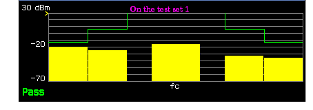
For the first test case, the Tx Spurious measurement is made on each test set for the carrier the test set is receiving, the four emission powers with the frequency offsets are measured. See An example graphical result for test case 1 of Test 2 on the two test sets .
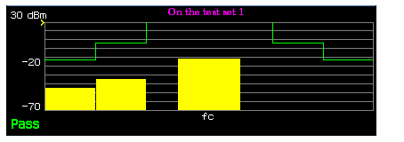
For the second test case, the Tx Spurious measurement is made on each test set at the fixed offsets outside the two carriers, but the emission powers between the two carriers are never measured. See An example graphical result for test case 2 of Test 2 on the two test sets .
-
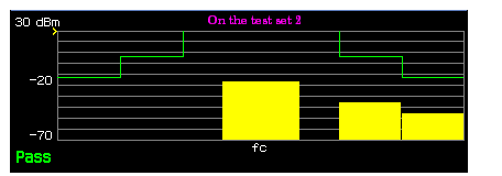
For Test 3 that support three carriers present, the measurement can only be performed on the Main unit. The test set measures the average power present at each frequency offset within a 30kHz or 1MHz filter centered on the offset frequency (30kHz for the adjacent and alternate offset and 1MHz for the second alternate offset), and then reports the absolute power of each frequency offset (the result is given in dBm). See
An example graphical result for Test 3 with three carriers
.
The adjacent offsets are fixed at ± 2.5 MHz at each side of the middle reverse channel, the alternate offsets could be set from ± 2.7 MHz to ± 3.47 MHz and the second alternate offsets could be set from ± 3.5 to ± 6.5 MHz with the alternate limit or second alternate limit changing with the offset when the Mask Control is set to
Auto.
You must establish an RMCTAP (for Subtype 3 Physical Layer) connection to perform the TX spurious emissions measurement with multi-carrier multi-unit (see Measuring TX Spurious Emissions for detailed procedure).
TX Spurious Emissions Measurement Parameters
-
Test Case Setup
Selects the test case that will be used when performing TX Spurious Emissions measurement with multi-carrier multi-unit . It is only available when the
Protocol Relis set toB(1xEV-DO-B)and theRelease B Physical Layer Subtypeis set toSubtype 3(See Protocol Rel or Release B Physical Layer Subtype ). -
Mask Control
When set to auto, the pass/fail limits for the spurious emissions at the adjacent and alternate channels are set as specified by C.S0033 3.1.2.4.1. For the Test 3, the emission powers alternate limit and second alternate limit will be changing with the offset, see Test3 Alternate Offset/Test3 Second Alternate Offset . When set to manual, you can set the pass/fail limits for the measurement. Separate pass/fail limits are provided for the adjacent and alternate channel measurements.
-
Adjacent Limit (in dBc)
Sets the pass/fail limit for the adjacent channel measurement (range is -65 to -10 dBc).
-
Alternate Limit (in dBc)
Sets the pass/fail limit for the alternate channel measurement (range is -65 to -10 dBc).
-
TestX Adjacent Limit
Sets the pass/fail limit for the adjacent channel measurement when the
Test Case Setupis set to Test X (where X refers to 1, 2 or 3) and theMask Controlis set toManual. -
TestX Alternate Limit
Sets the pass/fail limit for the alternate channel measurement when the
Test Case Setupis set to Test X (where X refers to 1, 2 or 3) and theMask Controlis set toManual. -
Test3 Second Alternate Limit
Sets the pass/fail limit for the second alternate channel measurement when the
Test Case Setupis set toTest 3and theMask Controlis set toManual. -
Test3 Alternate Offset/Test3 Second Alternate Offset
Sets the alternate offset or the second alternate offset of the test 3.
- Multi-Measurement Count - When ON, this enables averaging of the TX spurious emissions results. (See Statistical Measurement Results ).
- Trigger Arm - (see Trigger Arm (Single or Continuous) Description ).
- Timeout Time/State - (see Measurement Timeouts ).
TX Spurious Emissions Measurement Results
- Integrity Indicator - (see Integrity Indicator ).
- Pass/Fail Result: An overall pass/fail indicator is displayed on the measurement screen and is available via GPIB commands (see FETCh:CTXSpurious:MASK[:FAIL]? ). The pass/fail result indicates whether the spurious emissions for all adjacent and alternate channels are within limits.
-
Spurious Emissions for Adjacent and Alternate offsets:
- For TX Spurious Emissions measurement with a single test set , The test set returns the spurious emissions levels for all adjacent and alternate offsets. These spurious emissions levels are available from the measurement screen marker and via GPIB commands. (see FETCh:CTXSpurious<[:ALL]|:INTegrity>? ).
-
For
TX Spurious Emissions measurement with multi-carrier multi-unit
, For each test case, the test set returns the spurious emissions levels for all its adjacent and alternate offsets for its measurement. These spurious emissions levels are available from the measurement screen marker and via GPIB commands on each test set (see
FETCh:CTXSpurious<[:ALL]|:INTegrity>?
).
For the test case of the Test 2 (see An example graphical result for test case 2 of Test 2 on the two test sets ), only 2 emission results are effective for the each carrier. For the Test 3, the Spurious Emissions for the second Alternate Channels can only be queried by FETCh:CTXSpurious:EPOWer:ALTernate2:TEST3? .NOTE
The TX Spurious Emissions Measurement Screen
The TX Spurious Emissions measurement screen can display numeric results or a graphical display.
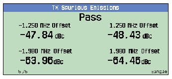
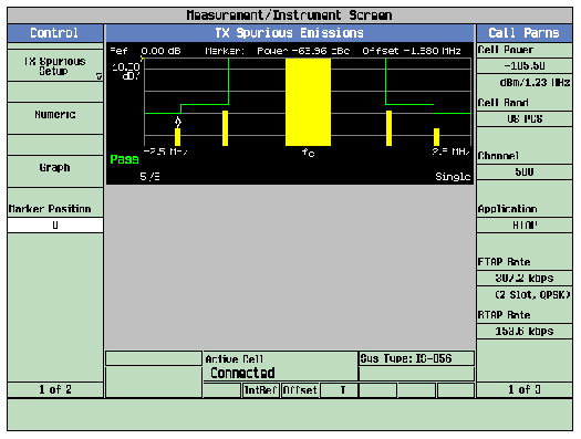
- The y-axis on the graphical display is fixed at -80 dBc/30 kHz to 0 dBc/30 kHz.
- The x-axis on the graphical display is fixed at -2.5 MHz to 2.5 MHz relative to the carrier frequency.
- Pass/fail limit lines are shown in green on the graphical display. These lines are set based on Mask Control and Adjacent/Alternate Limit (see TX Spurious Emissions Measurement Parameters ). If spurious emissions at any adjacent or alternate channel exceed a limit line, the word Fail appears on the display.
- The carrier is displayed in the center of the display as a solid yellow bar. The spurious emissions power at the four frequency offsets is displayed as yellow bars.
-
A marker is supplied to view the frequency offset and the spurious emission power
- If TX Spurious Emissions measurement with a single test set is performed, the marker can be positioned on each of the four frequency offsets. The spurious emissions for that frequency offset is then displayed.
-
If
TX Spurious Emissions measurement with multi-carrier multi-unit
is performed
- For Test 1, the marker can be positioned on each of the four frequency offsets and the power level relative to the in-channel power of each of the 4 offsets is displayed.
- For Test 2, the marker can be positioned on each of the four frequency offsets or the carrier channel at which the test set is receiving, the absolute emission power for each point is displayed. However if the frequency separation between the two carriers is less than the maximum possible frequency separation, the emission power that is between the two carriers is not displayed and will return 9.91E+37 (NAN) when queried with GPIB command.
- For Test 3, the marker can be positioned on each of the six frequency offsets or the three carrier frequencies in the middle, the absolute emission power for each point is displayed.
Calibrating the TX Spurious Emissions Measurement
The TX spurious emissions measurement is automatically calibrated during a channel power calibration. Follow the channel power calibration schedule and the TX spurious emissions measurement will be properly calibrated. Refer to Calibrating the Test Set for a description of channel power calibration.
Related Topics
GPIB Commands:
Manual Operation: Measuring TX Spurious Emissions
Programming a Tx Spurious Emissions Measurement
Tx Spurious Emissions Measurement Troubleshooting
C.S0029 Test Application Specification Description (TAP/ETAP/MCTAP)
