IS-856 Test Operating Mode
Last updated: November 29, 2010
- Overview
- Parameters for IS-856 Test Operating Mode
- Measurements supported by the test set in IS-856 Test operating mode
Overview
The test set's IS-856 Test operating mode is used when it is not possible, or not desired, to communicate via over-the-air signaling with the access terminal (AT), but forward link stimulus and reverse link measurements are still needed.
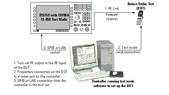
In IS-856 Test operating mode, the test set does not send any signaling information on the forward link. Any changes to the access terminal (AT) configuration, such as channel, MAC index, forward traffic data rate, etc., must be accomplished by directly sending commands to the AT from a system controller (usually a personal computer) through a proprietary digital interface.
Upon entry into IS-856 Test operating mode, the test set begins continuously transmitting a forward link signal which consists of forward channels such as pilot, MAC, and traffic channels. The PC controller is required to initiate the test mode in the AT, step the AT through the call setup process (such as acquire pilot, acquire sync, and demodulate forward traffic channel). When the AT synchronizes to the forward channels and successfully demodulates the forward link signal, the AT starts transmitting a corresponding reverse link signal. The AT's transmitter performance can then be measured using the suite of measurements shown when the Measurement selection key is pressed. A typical test setup is shown in the figure below.
Multi-carrier Test in IS-856 Test Operating Mode
In IS-856 Test operating mode, when the
Protocol Rel
is set to
B (1xEV-DO-B)
and the physical layer subtype is subtype 3, you can test the AT's multi-carrier performance using a single test set.
The test set in IS-856 Test operating mode provides a single forward link, thus only one carrier from the AT can be tested at a time. Before the multi-carrier measurement, set the Number of Active AT Carriers on the test set correctly so that it is consistent with the number of reverse carriers from the AT. Up to 3 carriers can be measured, one after another, by switching the operating channel.
To perform multi-carrier test in Active Cell operating mode, multiple test sets are required to be connected and configured correctly to provide multiple carriers. See Multi-carrier Multi-unit (MCMU) Overview .
Parameters for IS-856 Test Operating Mode
Most of the call processing parameters used in the Active Cell operating mode are also available in the IS-856 Test mode (see How Do I Change Parameters in IS-856 Test Operating Mode? for details).
The table below only shows the key parameters that are set differently while in the IS-856 Test mode and in the Active Cell mode.
|
5 - 63 (see MAC Index in IS-856 Test Operating Mode ) |
5-63 and 72-127 (see MAC Index in IS-856 Test Operating Mode ) |
5-63 (see MAC Index in Active Cell Operating Mode ) |
5-63 and 72-127 (see MAC Index in Active Cell Operating Mode ) |
|
| See F-Traffic Format |
See FTAP Rate . |
See F-Traffic Format and F-Traffic Config |
||
|
See Expected Reverse Data Rate in IS-856 Test Operating Mode . |
See R-Data Pkt Size |
See RTAP Rate . |
See R-Data Pkt Size |
|
|
To set a forward link frequency that does not correspond to a defined channel number, you can set the test set's RF generator frequency control to manual and enter a RF generator frequency manually. See CALL[:CELL]:CONTrol:DOWNlink:FREQuency:AUTO and CALL[:CELL]:RFGenerator:FREQuency . |
The test set's RF generator frequency can only be determined from the Band and Channel number corresponding to the standard definition. |
|||
|
Three modes are available, Alternating bits, All Up bits, All Down bits. See Reverse Closed Loop Power Control for description. |
Four modes are available, Active bits, Alternating bits, All Up bits, All Down bits. See Reverse Closed Loop Power Control for description. |
|||
|
You must set UATI ( UATI 024 , UATI Color Code ) or Long Code Mask to be used. For Subtype 3 Physical Layer, you must also set the Number of Active AT Carriers . |
UATI 024 and UATI Color Code are sent in the UATI Assignment message. |
|||
Measurements supported by the test set in IS-856 Test operating mode
|
Measurements (Applicable to both Subtype 0, Subtype 2 and Subtype 3 Physical Layer.) |
|
|---|---|
| Access Probe Power Measurement Description | |
| Channel Power Measurement Description | |
| Digital Average Power Measurement Description | |
| Waveform Quality + Code Domain Measurement Description | |
| TX Spurious Emissions Measurement Description | |
| Time Response of Open Loop Power Control (TROLPC) Measurement Description | |
| TX Dynamic Power Measurement Description | |
